Loading...
A. Purpose. The -COS overlay zone is intended to encourage mixed use development of medium- and high-density residential and commercial land uses and to promote increased residential density, and transportation patterns that do not rely solely on the automobile. The development standards of the -COS overlay zone are designed to encourage a safe and pleasant pedestrian environment with an attractive streetscape, and limited conflicts between vehicles and pedestrians.
B. Applicability. The -COS overlay zone is applied to land designated by the General Plan as either a corridor opportunity site or a downtown opportunity site.
C. Allowed Land Uses. Allowed land uses are determined by the primary zoning districts. Residential projects within the -COS must be developed at or above the midpoint of the allowable density range of the primary zoning district designation unless one or more of the following findings are made:
1. The proposed project does not include residential development;
2. Residences are integrated vertically in a mixed-use project;
3. Site considerations such as parcel size, configuration, environmental resources, or other features make achieving the midpoint infeasible or undesirable; or
4. Infrastructure constraints make achieving the midpoint impractical.
D. Development Standards. In addition to the standards of the primary zoning district and all other applicable provisions of these regulations, the following criteria apply:
1. Density. When associated with a residential base zoning district: 15 units/acre minimum, 70 units/acre maximum. When associated with an office or commercial base zoning district: Up to 60 units/acre.
2. Maximum Height Limit: 65 feet and unless the underlying zoning district permits a greater maximum height.
3. Off-Street Parking Reduction. Proposed development may provide off-street parking at a lower rate as provided by Chapter 19.70.
(Ord. 2185, 2427 §43, Ord. 2494 §31, Ord. 2600)
A. Purpose. The purpose of the -FS overlay zone is to encourage fraternity and sorority houses, as defined by Section 19.04.020, to be located in proximity to the California State University, Chico, campus and to preserve the neighborhood characteristics of the area.
B. Applicability. The -FS overlay zone may be combined with the R3, R4, and RMU residential zoning districts.
C. Allowable Land Uses. Any land use normally allowed in the primary zoning district may be allowed within the -FS overlay zone, subject to the land use permit requirements of the primary zoning district, except that fraternity and sorority houses shall be a permitted use upon the issuance of a fraternity/sorority house permit by the Director in compliance with Chapter 19.21 (Fraternity and Sorority House Permits).
(Ord. 2427 §43)(Ord. 2435 §31, Ord. 2494 §32)
A. Purpose. The purpose of the -FD overlay zone is to prevent environmental degradation, slope failure, increased erosion, sedimentation, and stormwater run-off; to preserve natural conditions in areas visible from public spaces; to retain topographic features and vegetation; to require site specific design solutions for unique topographic, landscape, and geotechnical settings; and to implement General Plan policies that apply to foothill development.
B. Applicability. The -FD overlay zone may be combined with any primary zoning district established by Section 19.40.010. The -FD overlay zone shall be applied and as shown on the Zoning Map for those properties at an elevation of 270 feet or greater.
C. Allowable Land Uses. Any land use normally allowed in the primary zoning district may be allowed within the -FD overlay zone.
D. Permit Requirements. Foothill development permit approval shall be required as set forth in Section 19.27.010. The requirements in Subdivisions (G) and (H) of this Section shall apply to projects for which a foothill development permit is required. They do not apply when a foothill development permit is not required.
E. Basis for Slope Determinations. For the purpose of this section, slope shall be computed on the natural slope of the land before any grading is commenced, as determined from a topographic map having a scale of not less than 1 inch equals 100 feet and a contour interval of not more than 5 feet.
F. Development Standards for Projects Within the -FD Overlay Zone. The following development standards apply to all projects within the -FD Overlay Zone.
1. Structure Height. Height shall be measured as the vertical distance to an imaginary plane located above the natural (pre-development) grade (See Figure 4-1). The height limit in the -FD overlay zone is 25 feet, with an allowance of up to 5 additional feet for chimneys, vents, other projecting architectural features, water tanks, and renewable energy devices. Heights less than 25 feet may be required along ridgelines and where prominently visible from public rights-of-way, parks, and other public spaces. Heights up to 35 feet may be allowed if the additional height does not impact public viewsheds.

2. Height measurement on downhill lot. Where the average slope of a parcel is greater than a 1-foot rise or fall in 7 feet of distance from the street elevation at the property line, one story shall be allowed on the downhill side of any structure in addition to the height allowed by the applicable zoning district; provided that the height of the structure shall not be increased above the limit established by the zoning district, measured from the finished street grade to the top of the roof (See Figure 4-2).

3. Setbacks Between Structures and Toes/Tops of Slopes.
a. On adjacent lots having a difference in finished grade elevation of 3 feet or more, the side yard shall be measured from the toe or top of slope to any structure, whichever is nearer.
b. On adjacent lots having a difference in finished grade elevation of 6 feet or more, the minimum distance between the toe or top of the slope, whichever is nearer, and any main structure shall be 15 feet.
c. The grading standards of Title 16 R (Building Standards) shall also apply and may result in greater setback requirements.
4. Clustered Development. In clustered development, dwelling units shall be grouped on more level or gently sloping terrain so as to reduce grading alterations on steeper slopes that shall be preserved in a natural state.
5. Maximum Density Calculation. To retain the natural features of hillsides, densities shall be reduced as slope increases. Each property to be developed shall be divided into cells of similar slope, using the average slope ranges listed in Table 4-16. The maximum density of the base zoning is then multiplied by the relevant reduction factor assigned to each cell to determine the maximum allowable density for each cell.
Average Slope Range | Density Reduction Factor |
0% to 10% | None |
10.1% to 15% | 0.9 |
15.1% to 20% | 0.8 |
20.1% to 25% | 0.6 |
25.1% to 30% | 0.4 |
Greater than 30% | No development |
6. Exterior Lighting. Lighting for new project sites and new streets shall be shielded to avoid glare and the spill of light to surrounding areas. Street lighting shall consist of multiple, shielded, low-intensity, pedestrian-scale lighting fixtures instead of fewer, taller fixtures.
7. Retaining Walls. Large retaining walls shall be broken into elements and terraces to avoid creating a uniform plane and landscaped to screen them from view (See Figure 4-3).

8. Street Design.
a. Street Layout. Streets shall follow the natural contours of the terrain, where possible, to minimize the need for grading. Cul-de-sacs and loop roads should be used where necessary to fit the natural contours and topography, subject to the approval of the City Engineer and Fire Department.
b. Reduced Street Widths. Streets may be designed without parking lanes when the result is a substantial decrease in cutting and/or filling. Streets may be reduced as provided for in Title 18R, Design Criteria and Improvement Standards.
9. Site and Structure Design. Site and structure design shall visually blend structures with the surrounding terrain.
a. Lot Line Locations. Lot lines should be placed at the top of slope areas.
b. Location of Structures. Structures should be sited in a manner that will:
(1) Minimize the creation of flat pads by using compact, split-level designs;
(2) Preserve vistas from public places; and
(3) Preserve visually significant rock outcroppings, natural hydrology, native plant materials, and areas of visual significance.
c. Architectural Design. Buildings shall demonstrate the following design principles:
a. Building scale that complements the character of the foothills and avoids massive forms that dominate public views of the foothills.
b. Varying setbacks, building heights, foundation designs, building forms, materials, and colors that blend structures into the terrain.
c. Building facades with varied planes and overhangs as a means to create changing shadow lines that further break up massive forms.
d. Incorporation of single story elements, setbacks, roof pitches, and landscaping for wall surfaces facing public viewsheds (See Figure 4-4).

e. Roof pitches placed to generally follow the angle of the slope, but with variation to avoid a monotonous appearance.
f. Medium to dark earth tone colors used for building elevations and roof materials.
g. Surface materials to blend with the landscaping and natural vegetation, such as textured stucco, wood, natural brick, and coarse block.
h. Rough-textured roof materials (and in some cases terra cotta and metal) in a muted, darker tone, including browns, grays and greens.
10. Grading and Drainage.
a. Grading shall be designed to conserve natural topographic features and appearances by retaining major natural topographic features (for example, canyons, knolls, ridgelines, and prominent landmarks), by minimizing the amount of cut and fill, and by means of landform grading to blend graded slopes and benches with the natural topography (See Figure 4-5).
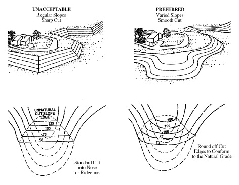
b. Grading plans shall identify slopes that are to be landform graded. "Landform grading" shall mean a contour grading method that creates artificial slopes with curves and varying slope ratios in the horizontal plane designed to simulate the appearance of surrounding natural terrain.
c. All graded areas shall be protected from wind and water erosion, in compliance Titles 16 (Buildings and Construction) and 16R (Building Standards). Interim erosion control plans, certified by the project engineer, shall be required.
d. Exposed slopes shall be replanted with non-invasive but self-sufficient trees, shrubs, and groundcover that are compatible with existing surrounding vegetation, to help blend manufactured and natural slopes and to protect slopes from soil erosion.
e. Grading that would create a slope exceeding a ratio of 3:1 requires a report and a stabilization study that indicates a greater permissible slope, unless it is determined by the Director that site conditions (as supported by data) do not warrant the report and study.
G. Required Plans and Reports. A subdivision or land use entitlement application for a site within the -FD overlay zone shall include the following documents as determined by the Director. If an applicant believes that any or all of the documents are not applicable, a written justification supported by factual information shall be submitted to the Director in order to justify an exception.
1. Topographic Map. A topographic map of the project site and land and structures within 100 feet of the project boundaries. Section drawings and/or elevations may be required where necessary to indicate those residences which may be affected in terms of view obstruction. The map shall be drawn to a scale of not less than 1 inch = 100 feet, with a maximum contour interval of 5 feet;
2. Project Plans. Plans of the proposed project, including property lines with recorded and proposed easements and public rights-of-way, existing and proposed contours, a representative cross-section showing existing and proposed conditions, ridgelines if applicable and the proposed treatment thereof, proposed erosion control and/or slope stabilization techniques, structure siting criteria and/or building envelopes, any height limitations, and any solar orientation considerations;
3. Slope Maps. Maps of existing and final slope depicting the following slope categories: 0-5 percent, 6-10 percent, 11-15 percent, 16-20 percent, and 21+ percent;
4. Soils Report. A soils engineering report, including data on the nature, distribution, and strengths of existing soils, approximate depth and location of shallow impervious layers; subsurface drainage; design criteria for identified corrective measures; and recommendations regarding existing conditions and proposed grading. The report shall be prepared by a registered engineer;
5. Geology Report. A geology report, including the surface and subsurface geology of the site, degree of seismic hazard, recommendations regarding the effect of geologic conditions on the proposed development, and recommended design criteria to mitigate any identified geologic hazards. The report shall be prepared by a registered geologist, civil engineer, or other qualified professional in engineering geology and may be combined with the soils report;
6. Hydrology Report. A hydrology report that identifies areas of possible inundation, downstream effects, natural drainage courses, primary groundwater recharge areas, effect of hydrologic conditions on the proposed development, recommendations regarding the adequacy of proposed facilities, and proposed solutions to mitigate identified hydrologic hazards. The report shall be prepared by a registered civil engineer experienced in hydrology and hydrologic investigation;
7. Biological Resource Assessment. A biological resource assessment of the subject site by a qualified biologist, including the location and species of trees over six inches in diameter at breast height; habitat type, such as annual grassland, permanent wetland, vernal pools/seasonal wetland or valley oak woodlands; and the occurrence of any special status species within the area;
8. Preliminary Landscaping Plan. A preliminary landscaping plan showing the size and location of existing trees over six inches in diameter at breast height, indicating any trees proposed for removal, and the type and extent of proposed conceptual landscaping;
9. Visual Simulation. A realistic, three-dimensional computer simulation of the proposed structures from multiple view points, including the use of story pole plans for structures along ridgelines or visible from public spaces; and
10. Other Information. Other information or application materials as may be deemed necessary by the Director.
H. Project Evaluation. The review authority's consideration of an application for foothill development shall include an evaluation of the following:
1. Consistency with the foothill development standards listed in this section;
2. The retention of natural topographic and prominent landmark features, significant ridgelines, natural rock outcroppings, prominent trees and woodlands, and other areas of special natural beauty; and
3. Site planning and structure design that minimizes impacts to public viewsheds.
(Ord. 2440 §36, Ord. 2494 §33, Ord. 2550 §2)
A. Purpose. The purpose of the -VE overlay zone is to implement the Valley's Edge Specific Plan.
B. Applicability. The -VE overlay zone may be combined with any primary zoning district established by Section 19.40.010 that exists within the bounds of the Valley's Edge Specific Plan area.
C. Allowable Land Uses. Land use allowances within the Valley's Edge Specific Plan area shall be determined as set forth in Appendix C of the Valley's Edge Specific Plan (Permitted and Conditionally Permitted Uses). If the Specific Plan is silent regarding a particular land use, then these Regulations shall be used to determine permitted land uses and permit requirements.
D. Development Standards. The development standards applicable to sites within the -VE overlay zone shall be as set forth in the Valley's Edge Specific Plan. If the Specific Plan is silent regarding a particular development standard, then these regulations shall be used to determine permitted land uses and permit requirements.
E. Administration and Permit Procedures. The administration and permit procedures contained in Divisions II and III, respectively, of these regulations shall be used to administer and process entitlement requests within the Valley's Edge Specific Plan area.
(Ord. 2583, §2)