Loading...
(A) Right of entry; inspection and sampling. The utility shall have the right to enter the premises of any establishment to determine whether the establishment is complying with all requirements of the FOG policy, any wastewater discharge permit or order issued hereunder. Establishments shall allow the utility ready access to all parts of the premises for the purposes of inspection, sampling, records examination and copying, and the performance of any additional duties during reasonable business hours.
(1) Where an establishment has security measures in force, which require proper identification and clearance before entry into its premises, the establishment shall make necessary arrangements with security so that, upon presentation of suitable identification, utility staff will be permitted to enter immediately for the purposes of performing specific responsibilities.
(2) The utility shall have the right to set up on the establishment property, or require installation of, such devices and/or structures as are necessary to conduct sampling and/or metering of the establishment’s operations.
(3) The utility may require the establishment to install monitoring equipment as necessary. The establishment’s sampling and monitoring equipment shall be maintained at all times in a safe and proper operating condition by the establishment at the establishment’s expense. All devices used to measure wastewater flow and quality shall be calibrated at least annually to ensure accuracy.
(4) Any temporary or permanent obstruction to safe and easy access to the establishment’s FOG control devices, interceptors or equipment to be inspected and/or sampled shall be promptly removed by the establishment at the written or verbal request of utility staff and shall not be replaced. The costs of clearing such access shall be born by the establishment.
(5) Unreasonable delays in allowing utility staff to access the establishment’s premises shall be a violation of this policy.
(B) New establishments. No new establishment will be allowed to initiate operations until a grease interceptor is installed, approved and inspected by the town. The town reserves the right to suspend service if the grease interceptor is not in compliance with the FOG policy.
(Ord. 2012-20, passed 8-22-2012) Penalty, see § 52.99
(A) No establishment shall discharge wastewater to the sanitary sewer system in violation of the FOG policy or the utility’s pretreatment discharge limitations.
(B) It shall be a violation of the FOG policy for any establishment to:
(1) Modify a grease interceptor structure without the consent or approval of the utility including alteration or removal of any flow constricting devices so as to cause flow to rise above the design capacity of the grease interceptor;
(2) Provide false maintenance records;
(3) Cause or permit the plugging, blocking or interference with a grease interceptor or permits others to cause such interference; and
(4) Not comply with the provisions of a FOG discharge permit or the FOG policy.
(C) No customer or establishment, including non-permitted establishments, shall discharge FOG to the sanitary sewer system in excess of 100 mg/l as total recoverable FOG, contribute to increased downstream maintenance of the sanitary sewer system due to a FOG discharge, or contribute to downstream backups or overflows due to FOG discharge. If such discharge occurs, the customer or establishment shall be considered in violation of this policy and subject to the remedies described herein.
(D) No establishment shall contribute or cause to be contributed into the grease interceptor or the sanitary sewer system any of the following:
(1) Hot water running continuously through grease interceptor;
(2) Concentrated alkaline or acidic solutions;
(3) Concentrated detergents, emulsifiers, de-emulsifiers, surface active agents, enzymes, degreasers, solvents or any type of product that will liquefy grease interceptor wastes;
(4) Any substance that may cause excessive foaming in the sanitary sewer system;
(5) Any substance capable of passing the solid or semi-solid contents of the grease interceptor to the sanitary sewer system;
(6) Hazardous wastes including concentrated cleaners, pesticides, herbicides, paints, solvents, gasoline or other petroleum products; or
(7) Waste fats, oils and grease not generated as part of the wastewater system.
(E) When the utility finds that a user has violated, or continues to violate, any provision of this policy, a wastewater discharge permit or order issued hereunder, or any other pretreatment standard or requirement, the utility may serve upon that user a written notice of violation (NOV). Within 20 days of the receipt of this notice, an explanation of the violation, verification of grease interceptor/trap cleaning, and a plan for the satisfactory correction and prevention thereof, to include specific required actions, shall be submitted by the user to the utility. Submission of this plan in no way relieves the user of liability for any violations occurring before or after receipt of the notice of violation. Nothing in this section shall limit the authority of the utility to take any action, including emergency actions or any other enforcement action, without first issuing a notice of violation. The utility may suspend sewer service when such suspension is required in order to stop an actual or threatened discharge that presents or may present an imminent or substantial endangerment to the health or welfare of persons or the environment.
(F) Any customer or establishment notified of a suspension of the sewer service shall immediately stop or eliminate the discharge. In the event of a failure of the customer or establishment to comply voluntarily with the suspension order, the utility shall take such steps as deemed necessary, including immediate termination of sewer service, to stop an actual or threatened discharge that presents or may present an imminent or substantial endangerment to the health or welfare of persons or the environment. The utility shall reinstate the sewer service when such conditions causing the suspension have passed or been eliminated. A detailed written statement submitted by the customer or establishment describing the cause(s) of the harmful discharge and the measure(s) taken to prevent any future occurrence shall be submitted to the utility within 15 days of the date of occurrence.
(G) Any customer or establishment may appeal the actions of the utility by submitting a notice of appeal to the utility within 14 days from the receipt of a suspension notice from the utility or other notice, requiring action, imposition of a fee, or notice of service termination. An appeal request will not delay action by the utility.
(H) The Utility Committee shall conduct a hearing on all appeals within 14 days of the receipt of notice of appeal. The notice of appeal shall state the technical grounds and objections for the appeal. At the hearing, the Utility Committee shall hear and investigate any objection that may be raised and take such action as may be appropriate under the facts and circumstances established.
(I) The Utility Committee shall render a decision within five business days of the date of the hearing. The customer or establishment requesting the appeal may petition the Town Council to review the decision or take other such action as permitted by applicable state law. The utility reserves the right to seek reimbursement of administrative and operational costs and legal fees resulting from enforcement of this policy.
(Ord. 2012-20, passed 8-22-2012) Penalty, see § 52.99
(A) Progression of penalty for violations of the FOG policy.
(1) When FOG policy violations are found at any restaurant or food preparation establishment the utility needs to take enforcement action to correct the issue. Violations may be as a result of on-site inspections by utility or County Health Department personnel, general complaints, consumer tips or observation of collection system problems from various utility department personnel.
(2) Establishments found to be violating the FOG policy shall be sent a notice of violation (NOV) that will outline the nature of the violation and the corrective measures that need to be taken along with a time frame in which the establishment must act. Failure to address the issue, failure to respond or failure to meet the stipulated time frame(s) will result in the issuance of a monetary penalty. The establishment shall also be responsible for reimbursing the utility for all costs incurred by the utility associated with the violation of the FOG policy, including, but not limited to, collection system maintenance/cleaning costs, property damage, administrative costs, engineering costs and legal costs.
(B) Fine structure.
(1) The fine structure shall be as follows:
(a) First NOV subjects the violator to a civil penalty of $250 if the violator fails to act upon a corrective recommendation within 20 working days. Costs incurred by the utility will also be applied. The 20 working days referenced may be reduced when significant water quality degradation has occurred or there is a high potential for such degradation to occur if left uncorrected. If corrective action is undertaken in the 20-day period, or a plan approved by the utility committee at its next scheduled meeting after the NOV is issued, the civil penalty will be waived; however, costs incurred by the utility will still be required to be paid.
(b) Second NOV for the same issue means that after the expiration of the time period for correction established in the first NOV, the condition or conditions constituting a violation in the first notice remain uncorrected or otherwise not compliant with the FOG policy. The violator shall be subject to an additional civil penalty of $500 if the violator fails to act upon a corrective recommendation within ten working days. Costs incurred by the utility will also be applied. The ten working days referenced here may be reduced when significant water quality degradation has occurred or there is a high potential for such degradation to occur if left uncorrected. If corrective action is undertaken in the ten-day period, or a plan approved by the utility committee at its next scheduled meeting after the NOV is issued, the civil penalty of $500 will be waived but not the penalty of $250 or the collection system cleaning costs.
(c) Third NOV for the same issue means that at any time after a ten-working day period for the correction of a second NOV has elapsed, the condition or conditions constituting the violation remain uncorrected and the violator will be subject to a civil penalty of $2,500 in addition to the original $250, and the second NOV of $500, and the costs incurred by the utility will be applied.
(d) Any further noncompliance will result in a daily fine of $250/day plus the costs incurred by the utility will be applied to the appropriate individual or individuals responsible for correcting the violating condition or conditions.
(2) The Sewer Office, after notification by the Plant Superintendent or his or her designee, will prepare the NOV and issue such notification to the affected property owner. Notification shall also be provided to the Sewer Committee and Town Council. In the event the affected property owner fails to comply with the NOV, the Sewer Office shall alert the Town Council that a fine or fines should now be levied and any further civil action that may be needed for failure of the establishment to submit payment. Payment will be collected by the utility administrative office.
(Ord. 2012-20, passed 8-22-2012)
(A) Grease interceptor sizing.
(1) This section of Appendix A is intended to be example guidance for the designer. The tank size shall be based on design criteria set forth in Bulletin S.E. 13 from the Indiana State Board of Health, latest edition.
(2) The recommended grease interceptor size may be calculated as follows:
Tank Size (in gallons) = Meals Served During Peak Hour x Waste Flow Rate Factor x Retention Time Factor x Storage Factor
(3) Components of the equation are:
(a) The peak meals served per hour = the maximum number of meals served in any given hour of kitchen operation (maximum seating capacity may be substituted for peak meals served per hour).
(b) The waste flow factor may be determined as one of the following:
1. For a commercial kitchen with a dishwashing machine, the waste flow factor = 6;
2. For a commercial kitchen without a dishwashing machine, the waste flow factor = 5;
3. For a single service kitchen (food served on, in, or with disposable service ware), the waste flow factor = 2; or
4. For food waste disposal only, the waste flow factor = 1.
(c) The retention time factor may be determined as one of the following:
1. For a commercial kitchen, the retention time factor = 2.4; or
2. For a single service kitchen, the retention time factor = 1.5.
(d) The storage factor may be determined as one of the following:
1. For a commercial kitchen, the storage factor = 0.125 X the hours/day of kitchen operation; or
2. For a single service kitchen, the storage factor = 1.5.
(4) Sample calculation no. 1.
(a) Calculate the size of a grease interceptor for a fast food restaurant that is open 24 hours per day and has a seating capacity of 66. There is no dishwasher and food is served with disposable service ware.
Tank Size (in gallons) = 66 x 2 x 1.5 x 1.5 Tank Size = 297 gallons |
(b) Note: The minimum size of a grease interceptor as stipulated by the FOG policy is 1,000 gallons. Therefore, a 1,000 gallon grease interceptor must be installed in this case.
(5) Sample calculation no. 2.
(a) Calculate the size of a grease interceptor for a commercial kitchen of a nursing home serving a maximum of 76 meals/hour. The kitchen is equipped with a dishwasher and the kitchen operates 15.5 hrs/day.
Tank Size (in gallons) = 76 x 6 x 2.4 x (0.125 x 15.5) Tank Size = 2,120 gallons |
(b) Note: The maximum size of a grease interceptor as stipulated by the FOG policy is 1,500 gallons. Therefore, two grease interceptors must be installed in series in this case.
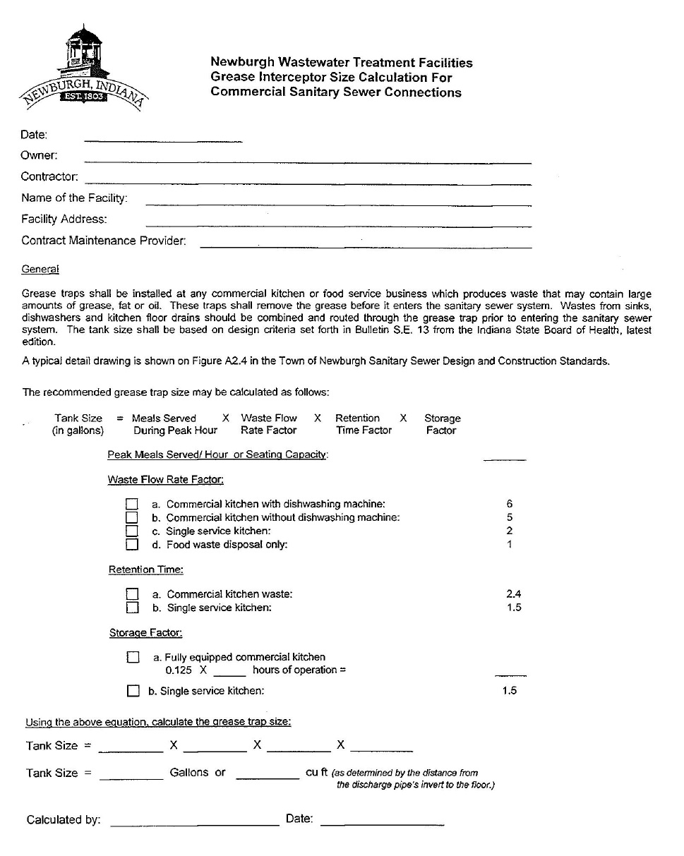
Newburgh Wastewater Treatment Facilities Grease Interceptor Size Calculation For Commercial Sanitary Sewer Connections |
Newburgh Wastewater Treatment Facilities Grease Interceptor Size Calculation For Commercial Sanitary Sewer Connections |
Date: |
Owner: |
Contractor: |
Name of the Facility: |
Facility Address: |
Contract Maintenance Provider: |
General |
Grease traps shall be installed at any commercial kitchen or food service business which produces waste that may contain large amounts of grease, fat or oil. These traps shall remove the grease before it enters the sanitary sewer system. Wastes from sinks, dishwashers and kitchen floor drains should be combined and routed through the grease trap prior to entering the sanitary sewer system. The tank size shall be based on design criteria set forth in Bulletin S.E. 13 from the Indiana State Board of Health, latest edition. |
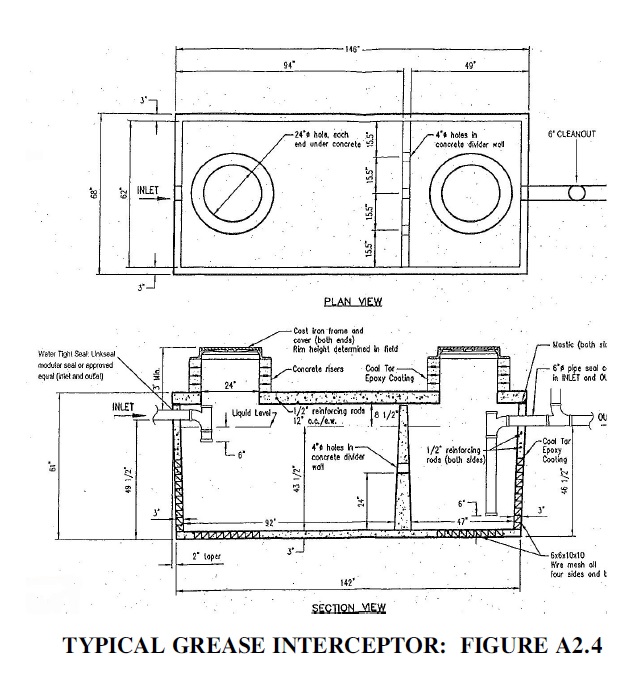
A typical detail drawing is shown on Figure A2.4 in the Town of Newburgh Sanitary Sewer Design and Construction Standards. |
The recommended grease trap size may be calculated as follows: |
Tank Size (in gallons) = Meals Served During Peak Hour x Waste Flow Rate Factor x Retention Time Factor x Storage Factor |
Peak Meals Served/Hour or Seating Capacity: |
Waste Flow Rate Factor: |
[ ] a.
Commercial kitchen with dishwashing machine: 6
|
[ ]
b. Commercial kitchen without dishwashing machine: 5
|
[ ]
c. Single service kitchen: 2
|
[ ]
d. Food waste disposal only: 1
|
Retention Time: |
[ ] a. Commercial kitchen waste 2.4 |
[ ] b. Single service kitchen: 1.5 |
Storage Factor: |
[ ] a. Fully equipped commercial kitchen |
0.125 x hours of operation = |
[ ] b. Single service kitchen: 1.5 |
Using the above equation, calculate the grease trap size: |
Tank Size = x x x |
Tank Size = Gallons or CU ft. (as determined by the distance from the discharge pipe’s invert to the floor.) |
Calculated by: Date: |
Notes:
1. All buried exterior lank surfaces shall be coated with ten ml. thickness coal tar epoxy.
2. All lateral piping shall be gasketed, six in. SDR 26 PVC.
3. Internal piping may be glue joint.
4. All tank joints shall be provided with water tight seals.
5. The minimum setback from the bottom of the building foundation to the bottom of the interceptor excavation shall be one to one.
6. The length to width ratio for the tank shall be two to one.
7. A cleanout shall be required in the discharge pipe within three feet of the tank.
TYPICAL GREASE INTERCEPTOR: FIGURE A2.4
(B) Internal grease tap sizing. Grease traps may be substituted for grease interceptors as provided in § 52.01(E) and (F) of the FOG policy. When grease traps are required by the utility, each grease trap shall have an approved rate of flow, which is not less than that given in the following grease trap sizing table for the total number of connected fixtures or as calculated using the sum of all modified flow rates for each fixture (modified flow rates for each fixture = gpm/fixture x the fixture rating). No more than four fixtures may be connected to one grease trap and dishwashers should have dedicated grease traps.
(1) Grease trap sizing table.
Table A | ||||
Total Number of Fixtures Connected | Maximum Total Capacity (Volume) of Fixtures | Required Rate of Flow (gallons/ minute) | Grease Retention Capacity (pounds) | |
(gallons) | (cubic feet) | |||
1 | 50 | 6.7 | 20 | 40 |
2 | 62 | 8.3 | 25 | 50 |
3 | 87 | 11.6 | 35 | 70 |
4 | 125 | 16.7 | 50 | 100
|
(2) Calculating the modified flow rates of various kitchen fixtures.
Modified flow rate = gpm/fixture x the fixture rating
(a) GPM/fixture. This is derived from the Manning formula. It takes into account the slope; roughness of the pipe (plastic) used and pipe diameter size. The drainage rates of various pipe diameter sizes are:
1. 0.5 inch pipe diameter = 0.8 GPM/fixture;
2. 1.0 inch pipe diameter = 5.0 GPM/fixture;
3. 1.5 inch pipe diameter =15 GPM/fixture;
4. 2.0 inch pipe diameter = 33 GPM/fixture;
5. 2.5 inch pipe diameter = 59 GPM/fixture; and
6. 3.0 inch pipe diameter = 93 GPM/fixture.
(b) Fixture ratings of grease-laden waste streams. Fixtures that have more grease in their waste stream receive higher values while less grease corresponds to a lower value. Common commercial kitchen fixtures and their corresponding rating (for each) are as follows:
Kitchen Fixture | Rating |
Kitchen Fixture | Rating |
1 or 2 compartment meat prep sink | 0.75 |
1 or 2 compartment vegetable prep sink | 0.25 |
2, 3, or 4 compartment pot sink | 1.0 |
Can wash | 0.25 |
Floor drain | 0.00 |
Mop sink | 0.25 |
Pre-rinse sink | 0.5 |
(c) Example calculations of fixture modified flow rates. A restaurant’s kitchen is supplied with the following fixtures. What is the modified flow rate for each fixture?
1. A two compartment pot sink with a one and one-half inch drain.
Fixture modified flow rate = 15 x 1.0 fixture modified flow rate = 15 gpm |
2. A two compartment vegetable prep sink with a one and one-half inch drain.
Fixture modified flow rate = 15 x 0.25 fixture modified flow rate = 3.75 gpm |
3. A mop sink with a two inch drain.
Fixture modified flow rate = 33 x 0.25 fixture modified flow rate = 8.25 gpm |
4. A dishwasher with a manufacture’s rated maximum discharge capacity of 10.0 gpm.
Fixture modified flow rate = 10.0 gpm |
(3) Example grease trap size determination.
(a) Given the information in divisions (B)(2)(c)1., (B)(2)(c)2., (B)(2)(c)3. and (B)(2)(c)4., the grease trap size(s) may be determined as follows:
1. Using Table A and number of fixtures. Using Table A, three fixtures require a grease trap with a flow rating of 35 gpm and a grease retention capacity of 70 pounds. Per § 52.03(K) of the policy, the dishwasher will require an additional grease trap capable of receiving ten gpm. In this case, the dishwasher will require the installation of a second grease trap which meets the minimum requirements of § 52.03(D). A grease trap with a flow rating of 20 gpm and a grease retention capacity of 40 pounds (per Table A) is required for the dishwasher.
2. Using Table A and fixture modified flow rates.
a. When using fixture modified flow rates, the size is determined using Table A and the sum of all fixture modified flow rates flowing into the grease trap:
15 gpm + 3.75 gpm + 8.25 gpm = 27 gpm |
b. In this case, 27 gpm is the minimum flow rating required, and, when this is compared to Table A, a 35 gpm grease trap will be required with a grease retention capacity of 40 pounds. The dishwasher will require the installation of a second grease trap as determined in division (B)(3)(a) above.
(Ord. 2012-20, passed 8-22-2012)
Town of Newburgh
Best Management Practices
Fats, Oil, and Grease (FOG)
Best Management Practices (BMPs)
For Food Service Facilities
Best Management Practices
Fats, Oil, and Grease (FOG)
Best Management Practices (BMPs)
For Food Service Facilities
(A) Information, pollution prevention and compliance information. Fats, oil and grease (FOG) can have negative impacts on wastewater collection and treatment systems. Most wastewater collection system blockages can be traced to FOG. Blockages in the wastewater collection system are serious, causing sewage spills, manhole overflows or sewage backups in homes and businesses. This manual is written to provide restaurant and fast food business managers and owners with information about FOG pollution prevention techniques focused on their businesses, effective in both reducing maintenance costs for business owners, and preventing oil and grease discharges to the sewer system. The discharge of FOG to the sewer system is illegal. Ensuring that grease trap and grease interceptors are properly installed and most importantly, properly maintained, is the key to avoiding enforcement action against your business. This manual focuses on proper maintenance of grease traps and interceptors, and includes inspection checklists for the business owner/manager as a guide to how and what town wastewater treatment utility (utility) pretreatment inspectors will be checking during an on site inspection.
(B) Manual contents.
(1) Manual contents includes:
(a) Frequently asked questions (FAQs);
(b) Best management practices (BMPs);
(c) Prohibitions;
(d) How it works;
(e) Maintenance; and
(f) Compliance inspection and installation checklists.
(2) Knowledgeable business managers can effectively prevent oil and grease buildup and associated problems for both the sewerage agency and the restaurant owner.
(C) Frequently asked questions about FOG.
(1) Frequently asked questions.
(a) Why is grease a problem?
(b) Do I need a grease interceptor or trap?
(c) Who determines if I need a grease trap or interceptor?
(d) Do I have a grease interceptor or trap?
(e) What is a grease trap and how does it work?
(f) What is a grease interceptor?
(g) How do I clean my grease trap or interceptor?
(h) Can you recommend a grease interceptor maintenance schedule?
(i) What if I don’t take care of my grease trap or interceptor?
(j) What are the criteria for inspecting grease traps?
(2) Why is grease a problem? Large amounts of oil and grease in the wastewater cause trouble in the collection system pipes. It decreases pipe capacity and, therefore, requires that piping systems be cleaned more often raising costs for all ratepayers. Oil and grease also hamper effective treatment at the wastewater treatment plant. Grease may not appear harmful but it congeals and causes nauseous mats on the surface of settling tanks, digesters and the interior of pipes and other surfaces which may cause a shutdown of wastewater treatment units. Problems caused by wastes from restaurants and other grease producing establishments are the reason the town wastewater treatment utility requires the installation of pretreatment equipment, commonly known as grease traps or interceptors.
(3) Do I need a grease interceptor or trap? Any establishment that introduces wastewater containing grease or oil into the sewage system is required to install an interceptor or in limited cases, an interior grease trap (point source). Interceptors are usually required for high volume fast food or full menu establishments and large commercial establishments such as hotels, hospitals, factories or school kitchens. In some instances, interior grease traps may be allowed for small volume fast food or take-out restaurants with limited menus, paper plate service, minimum dishwashing and/or minimal seating capacity.
(4) Who determines if I need a grease trap or interceptor? When waste pretreatment is required by the utility, an approved grease trap or interceptor shall be installed according to the Town Sanitary Sewer Design and Construction Standards and the town fats, oil and grease policy. The utility staff will assist the establishment in determining if a grease trap or interceptor is required and the appropriate sizing. The utility’s inspectors make routine periodic inspections to verify that mandatory maintenance BMPs are being implemented. These BMPs are fully enforceable under the utility’s regulations.
(5) Do I have a grease interceptor or trap? If you are uncertain whether your establishment has a grease interceptor or trap, you should contact the utility for assistance. You may request a “voluntary compliance” visit by the utility’s inspector without risk of an enforcement action. You will be required to comply with any requests for cleaning or other maintenance.
(6) What is a grease trap and how does it work? A grease trap is typically located under the sink or other kitchen fixture to which it is connected. Baffles in the trap interior slow the wastewater down long enough for the grease to separate and rise to the surface. The grease can then be removed and disposed of properly. Passive traps must be cleaned manually. Electro-mechanical devices require less manual maintenance and are more efficient because accumulated FOG is automatically removed daily.
(7) What is a grease interceptor? An interceptor is a buried vault with a minimum capacity of between 1,000 and 1,500 gallons located on the exterior of the building. The vault includes a minimum of two compartments, and flow between each compartment is through a configuration of pipe fittings designed to allow for solids settling and grease retention. The capacity of the interceptor provides adequate detention time so that the wastewater has time to cool, allowing grease to separate and rise to the surface where it accumulates until the interceptor is cleaned. See How it Works section in this document for a description of how the various components of a grease interceptor function.
(8) How do I clean my grease trap or interceptor? Refer to Grease Trap and Interceptor Maintenance section in this document.
(9) Can you recommend a grease interceptor maintenance schedule? Based on historical inspection observations and established best management practices, most grease interceptors need to be cleaned every 60 to 90 days. Some establishments will find it necessary to clean their traps more often. In some instances, light menu, low volume facilities may be able to clean less frequently. Only rarely does a facility have to pump less frequently than every six months. Demonstrating through accurate record keeping that a less frequent cleaning schedule is fully adequate is the responsibility of you the business owner/manager. It is not the utility’s responsibility. Securing a service contract with a qualified pumping contractor for routine inspection and cleaning as needed is the best way to avoid enforcement action by the utility. Waiting until the utility’s inspector arrives on site and requires you to clean your interceptor is not an acceptable best management practice and will result in an enforcement action.
(10) What if I don’t take care of my grease trap or interceptor? Failure to implement the required FOG BMPs is a violation of the utility’s regulations. Additionally, if the establishment fails to adequately maintain its trap or interceptor, it will eventually encounter a maintenance problem with a plugged sewer line. The blockage can create a sewer backup situation and ultimately a potential health problem in the establishment. If the problem is in the building sewer line, then the establishment has direct responsibility for paying for the maintenance. If the blockage or restriction occurs in the utility’s sewer main then the establishment will have to pay for the utility’s line cleaning maintenance costs. The discharge of grease to a sanitary sewer line in amounts “which will or may cause obstruction” is a violation of the utility’s Regulations and will result in enforcement action including cost recovery, fines and/or penalties.
(11) What are the criteria for inspecting grease traps/interceptors ?
(a) All food service establishments are inspected for compliance with BMPs. The following general criteria are used by pretreatment inspectors during trap or interceptor evaluation and are offered here for information purposes only. The judgment of the on-site inspector is final.
Percent of Hydraulic Capacity | Condition | Inspector Action |
25% | Good | Check records for last date cleaned. Maintain normal schedule. |
25—50% | Fair to poor | Check next scheduled date for cleaning. Advise facility to schedule soon. Order revision of cleaning schedule as necessary. |
>50% | Noncompliance | Order immediate cleaning. Order prescribed cleaning schedule. Facility to call for re-inspection. |
(b) If the trap is in fair to poor condition, the facility may be advised to schedule a cleaning event in the near future. The cleaning frequency schedule may need to be increased. If the trap is in noncompliance, the facility is issued a compliance order to have it cleaned immediately. The facility is required to call for re-inspection within seven days to verify that the trap or grease interceptor has been properly cleaned. An enforcement action including fines and/or penalties will be taken against facilities found in noncompliance a second time.
(D) Best management practices (BMPs).
(1) Required FOG BMPs - maintain grease traps and interceptors.
BMP | Reason | Benefits to Food Service Establishment | Pretreatment Inspection Checks |
Clean grease interceptors routinely. 60 to 90 day cleaning schedules are standard unless the facility can demonstrate a less frequent schedule is adequate. Securing a service contract with a qualified pumping contractor for routine inspection and cleaning as needed is strongly advised. | Grease interceptors must be cleaned routinely to ensure that grease accumulation does not limit retention time and separation efficiency resulting in pass through of grease to tie sewer. Waiting until an inspector arrives on site and requires you to clean your interceptor is not an acceptable BMP and may result in an enforcement action. | The cleaning frequency is a function of the type of establishment the size of the interceptor, and the volume of flow discharged by the establishment. Routine cleaning is a required BMP. Avoid utility enforcement action. | 50% of the interceptor capacity as a combination of grease (top) and sediment (bottom) requires immediate cleaning. |
Clean undersink passive type grease traps weekly unless facility can demonstrate a less frequent schedule is adequate. Accurate cleaning records or logs are required to be kept on site. | If passive grease traps are more than 50% full when cleaned weekly, the cleaning frequency needs to be increased. | Weekly cleaning of undersink grease traps serves to limit risk of enforcement action by the utility. If the grease trap is not providing adequate protection, the utility will require installation of additional grease abatement equipment | Visually inspect the undersink grease trap for flow restrictor. Inspect cleaning records. |
Electromechanical automatic traps - empty oil buckets daily. Clean solids strainer daily. Never remove flow restrictor. Clean wiper blades per the manufacturer’s recommended cleaning frequency. | Solids take up capacity and can cause odors. (See electromechanical trap maintenance section further down in this document.) | Adequate maintenance ensures maximum efficiency. | Check that electromechanical trap is plugged in and timer is set. Visually inspect the device for flow restrictor. Check solids basket. Inspect cleaning and maintenance records. |
Keep a maintenance log. A sample copy is available for reprint at the end of this document. | The maintenance log serves as a record of the frequency and volume of cleaning the interceptor. It is required by the pretreatment program to ensure that grease trap/ interceptor maintenance is performed on a regular basis. | The maintenance log serves as a record of cleaning frequency and can help the establishment manager optimize cleaning frequency to reduce cost. | Inspect maintenance log. Provide the establishment with a sample maintenance log if it does not have one. Confirm the maintenance log with the grease hauler identified. |
(2) Recommended FOG BMPs for your kitchen operations.
BMP | Reason | Benefits to Food Service Establishment | Pretreatment Inspector Checks |
BMP | Reason | Benefits to Food Service Establishment | Pretreatment Inspector Checks |
Witness all grease trap or interceptor cleaning and maintenance activities to ensure the device is properly operating. | The facility manager inspects the cleaning operation and ensures it is consistent with the procedures in the section on grease trap and interceptor maintenance. | The establishment will ensure it is getting value for the cost of cleaning the grease trap or interceptor. Otherwise the establishment may be paying for cleaning more often than necessary. | Check condition of grease interceptor. Check for submerged inlet and outlet. Check for evidence of grease in outlet pipe. Check for evidence of overflow or blockage. |
Train kitchen staff and other employees about how they can help ensure BMPs are implemented. | People are more willing to support an effort if they understand the basis for it. | All of the subsequent benefits of BMPs will have a better chance of being implemented and you can avoid enforcement actions. | Talk to the establishment manager about the training program that he or she has implemented. |
Post “No Grease” signs above sinks and on the front of dishwashers. | Signs serve as a constant reminder for staff working in kitchens. | These reminders will help minimize grease discharge to the traps and interceptors and reduce the cost of cleaning and disposal. | Check appropriate locations of “No Grease” signs. |
Use a low temp chemical sanitization type dishwasher. Follow Warrick County Health Department regulations for sanitizing. | Temperatures can be set at 120°F or less depending on type of chemical sanitizer used. The Uniform Plumbing Code (UPC) prohibits discharging any type dishwasher to grease traps. | The food service establishment will reduce its costs for the energy - gas or electric - for heating the water. | Check boiler or hot water heater discharge temperature. Measure the temperature of the hot water being discharged from the closest sink. |
Use a three-sink dishwashing system, which includes sinks for washing, rinsing and chemical sanitizing. Follow Warrick County Hearth Department regulations for sanitizing. | A hot water sanitization type dishwasher typically requires a minimum temperature of 165°F for stationary rack, single temperature machines. 180°F for all other type systems. | The food service establishment will reduce its costs for the energy - gas or electric - for heating the water for the mechanical dishwasher and for operating the dishwasher. | Measure temperature of the hot water at the three-sink system. Note: The Uniform Plumbing Code (UPC) prohibits the discharge of dishwasher water to grease traps. |
Recycle waste cooking oil. | This is a good recycling opportunity. There are several waste oil recyclers serving the town area. | Liquid wastes cannot go into dumpsters. Low cost for proper handling of the waste material. | Obtain name of recycler used. Review recycling records. Confirm records with recycler. |
“Dry wipe” pots, pans and dishware prior to dishwashing. | By “dry wiping” and disposing in garbage receptacles, the material will not be sent to the grease traps and interceptors. | This helps keep grease from going to grease traps and interceptors, which will require less frequent cleaning, reducing maintenance costs. | Observe dishwashing practices. |
Scrape plates to dry trash. Use screens in your sinks to catch food waste. Dispose of food waste by recycling and/or by disposing to a dumpster as solid waste. | Some recyclers will take food waste for animal feed. The food waste can be disposed to the dumpster. | Recycling of food wastes will reduce the cost of solid waste disposal. Solid waste disposal of food waste will reduce the frequency and cost of grease trap and interceptor cleaning. | Inspect dumpster corral for cleanliness. Check bottom of grease interceptor for solids accumulation. |
(3) Prevent FOG from entering the storm drain system.
BMP | Reason | Benefits to Food Service Establishment | Pretreatment Inspection Tips |
Cover outdoor grease and oil storage containers. Secure barrels to an outside wall or post to prevent tipping spills. | Uncovered grease and oil storage containers can collect rainwater. Since grease and oil float, the rainwater can cause an overflow onto the ground. Such an overflow will eventually reach the storm water system and nearby streams. | The discharge of grease and oil to the storm drain system can impact rivers and streams. Discharge of grease and oil to the storm drain will result in a clean up order at your expense and possible legal penalties or fines. | Observe storage area for signs of oil and grease. Inspect containers for covers. Remove covers to ensure containers have not overflowed and do not have excess water. |
Locate grease dumpsters and storage containers away from storm drain catch basins. Be aware of oil and grease dripped on the ground while carrying waste to the dumpster, as well as oil and grease that may “ooze” from the dumpster. | The farther away from the catch basin, the more time someone has to clean up spills or drainage prior to entering the storm drain system. | The discharge of grease and oil to the storm drain system can impact rivers and streams. Discharge of grease and oil to the storm drain will result in a clean up order at your expense and possible legal penalties or fines. | Observe storage area for signs of oil and grease. Inspect the closest catch basin for signs of accumulated grease and oil. |
Use absorbent pads or other material in the storm drain catch basins if grease dumpsters and containers must be located nearby. Use absorbent materials such as “kitty litter” and sweep up for disposal to dumpster. | Absorbent pads and other materials can serve as an effective barrier to grease and oil entering the storm drain system. | The discharge of grease and oil to the storm drain system can impact rivers and streams. Discharge of grease and oil to the storm drain will result in a clean up order at your expense and possible legal penalties or fines. | Check the nearest catch basin and drainage paths for signs of grease and oil. Require absorbent pads if the basin is within 20 feet of grease dumpsters or containers or if there are signs of grease in the catch basin at any distance. |
Routinely clean kitchen exhaust system filters inside at sinks connected to grease a trap or outside interceptor. | If grease and oil escape through the kitchen exhaust system, it can accumulate on the roof of the establishment and eventually enter the storm drain system when it rains. The discharge of grease and oil to the storm drain system can impact rivers and streams. | Discharge of grease and oil to the storm drain will result in a clean up order at your expense and possible legal penalties or fines. Ensure your hood cleaning contractor properly handles the wastewater - you’re responsible! | Inspect roof downspouts for signs of oil and grease. Require a maintenance schedule and records for cleaning exhaust filters. |
(4) Prohibitions relating to discharge of fats, oil and grease.
Prohibitions | Basis |
Discharge fats, oil and grease in amounts that “can or may” cause an obstruction to the flow in a sewer is prohibited. | Grease can solidify and trap other solid particles to completely plug the wastewater collection system. |
Commercial garbage disposers and grinders are prohibited. | These materials in combination or alone can cause blockages and other operations and maintenance problems in the wastewater collection and treatment system. |
Do not discharge wastewater with temperatures in excess of 140°F to any grease traps. Add cold water to manual washing triple sink sanitizing water before discharge through a grease trap. Mechanical dishwasher is required to be plumbed to outside grease interceptor. It may be plumbed to grease traps only by special permission. | Temperatures in excess of 140°F will dissolve and flush grease out of the trap. Grease can re-congeal and cause blockages farther downstream in the sanitary sewer collection system as the water cools. |
Direct introduction of enzymes, bio-additives, emulsifying agents or similar chemicals is prohibited. | These agents can cause interference and pass through resulting in grease being discharged to the sewer system. |
Do not clean kitchen equipment outdoors. | Grease and dirt will be washed off the equipment and enter the storm drain system. |
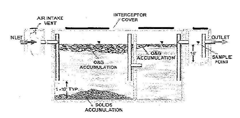
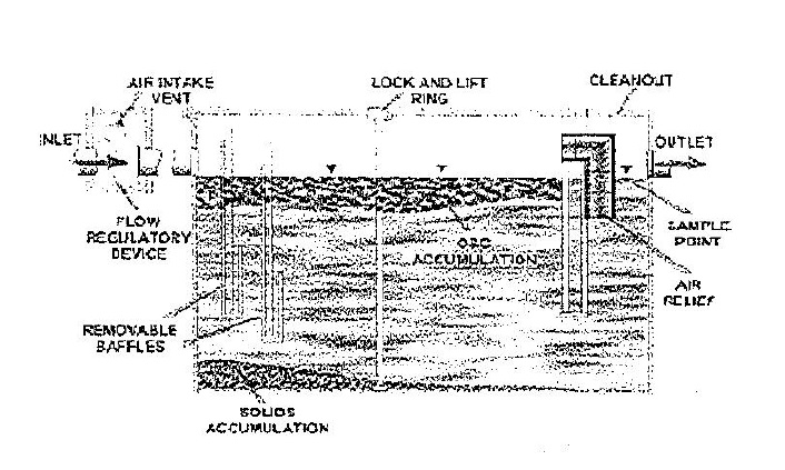
(5) How it works - grease interceptor.
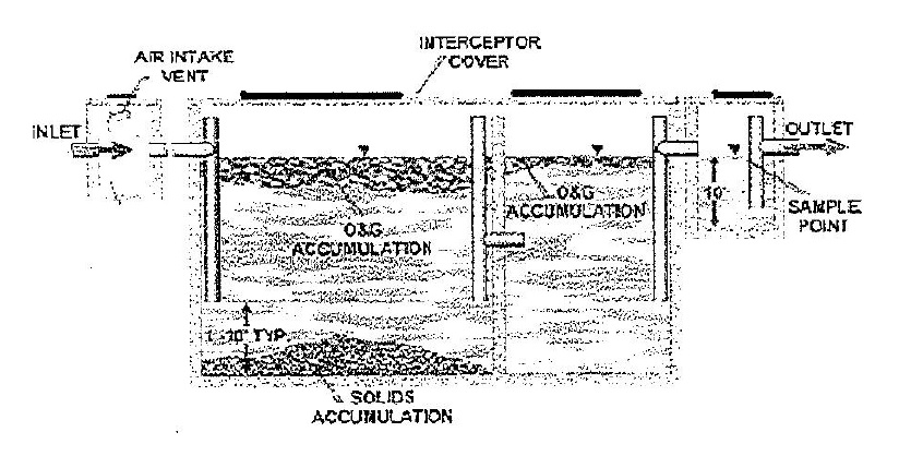
(a) Flow from undersink grease traps or directly from plumbing fixtures enters the grease interceptor. The UPC requires that all flow entering the interceptor must enter through the inlet pipe.
(b) An air intake valve allows air into the open space of the grease interceptor to prevent siphonage and backpressure.
(c) Oil and grease floats on the water surface and accumulates behind the grease retaining fittings and the wall separating the compartments. The oil and grease will be removed during routine grease interceptor cleaning.
(d) Solids in the wastewater that do not float will be deposited on the bottom of the grease interceptor and will need to be removed during routine grease interceptor cleaning.
(e) Grease retaining fittings extend down into the water to within 12 inches of the bottom of the interceptor. Because grease floats, it generally does not enter the fitting and is not carried into the next compartment. The fittings also extend above the water surface to provide air relief.
(f) Some interceptors have a sample box so that inspectors or employees of the establishment can periodically take effluent samples. Having a sample box is recommended but not required by the utility.
(g) Flow exits the interceptor through the outlet pipe and continues on to the sanitary sewer system.
(6) Grease trap and interceptor maintenance.
(a) Generally.
1. Grease trap maintenance is usually performed by maintenance staff, or other employees of the establishment. Grease interceptor (GI) maintenance, which is usually performed by permitted haulers, consists of removing the entire volume (liquids and solids) from the GI and properly disposing of the material in accordance with all federal, state and/or local laws. When performed properly and at the appropriate frequency, grease interceptor and trap maintenance can greatly reduce the discharge of FOG into the wastewater collection system. The required maintenance frequency for grease interceptors and traps depends greatly on the amount of FOG a facility generates as well as any best management practices (BMPs) that the establishment implements to reduce the FOG discharged into the sanitary sewer system. In many cases, an establishment that implements BMPs will realize financial benefit through a reduction in their required grease interceptor and trap maintenance frequency. Refer to the best management practices tables in this document for examples of BMPs that FOG generating establishments should implement.
2. Warning! Do not use hot water, enzymes, bio-additives, emulsifying agents or similar chemical agents in lieu of physical cleaning of grease traps and interceptors.
(b) Grease interceptor maintenance. Grease interceptors, due to their size, will usually be cleaned by grease haulers or recyclers. Licensed septic haulers can also pump out grease interceptors and haul the waste to a regulated facility. Septic haulers are required to be permitted by the state. A proper maintenance procedure for a grease interceptor is outlined below:
Step | Action |
l. | Review records of last cleaning. Most units require cleaning every 60 to 90 days. |
2. | Contact a grease hauler for cleaning. See: Grease Interceptor Cleaning Contractors. |
3. | Record the volume of grease removed on the maintenance log or retain contractor receipt. |
(c) Electro-mechanical trap maintenance. A proper maintenance procedure for these automatic grease removal devices includes:
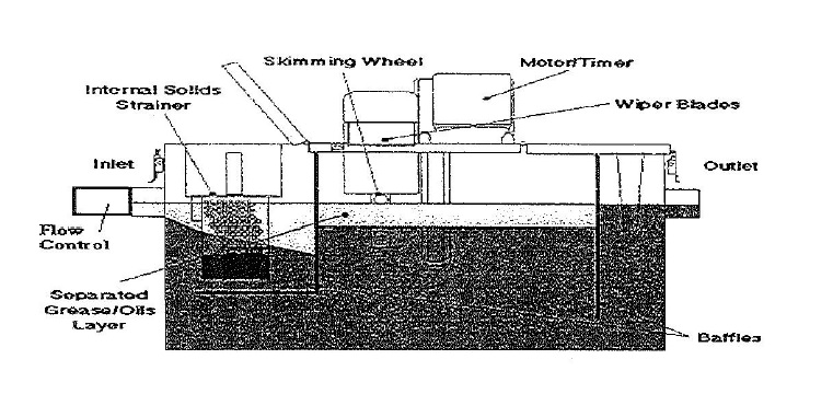
Step | Action |
1. | Empty - solids strainer and the outside grease cup daily |
2. | Clean - wiper blades and grease outlet trough per the manufacturer’s recommended cleaning frequency. |
3. | Clean - the entire unit, including sediment at the bottom, a minimum of monthly. |
4. | Replace - wiper blades every six months to ensure proper operating condition. |
5. | Check - It doesn’t work if it’s not plugged in and if the auto timer is not set properly. |
(d) Passive grease trap maintenance. A proper maintenance procedure for a grease trap is outlined below:
Step | Action |
1. | Bail out any water in the trap to facilitate cleaning. The water should be discharged to the sanitary sewer system. |
2. | Remove baffles if possible. |
3. | Dip the accumulated grease out of the interceptor and deposit in a watertight container. Remove all solids from the bottom of the trap. Scrape the sides, the lid and the baffles with a putty knife to remove as much of the grease as possible. |
4. | Mix grease and solid materials with “kitty litter” and dispose to dumpster. |
5. | Replace the baffle and the lid. |
6. | Record the date, name of attendant and volume of grease removed on the maintenance top (copy at end of this document). |
(E) Inspection checklist.
Item | Item Description | Field Data | Compliance Status |
Item | Item Description | Field Data | Compliance Status |
1. | The establishment has implemented a training program to ensure that the BMPs are followed. | ||
2. | “No Grease” signs are posted in appropriate locations. | ||
3. | The establishment recycles waste cooking oil and can provide records of this. | ||
4. | Water temperatures at all sinks, especially the pre-rinse sink before the mechanical dishwasher or the sinks in the three-sink system are less than 140°F. Measure and record temperature | ||
5. | The establishment “dry wipes” pots, pans, and dishware prior to rinsing and washing. | ||
6. | Food waste is disposed of by recycling or solid waste removal and is not discharged to the grease traps or interceptors. | ||
7. | Grease trap(s) is cleaned regularly. Note and record the frequency of cleaning. | ||
8. | Grease trap cleaning frequency is documented on a maintenance log (copy at end of this document). | ||
9. | Grease interceptor does not contain greater than one-third the depth in grease accumulation. Estimate and record amount of grease in interceptor. | ||
10. | Grease interceptor does not contain greater than one-fourth the depth in sediment accumulation. Estimate and record amount of sediment in interceptor if possible. | ||
11. | Grease interceptor is cleaned and maintained regularly. Note and record frequency of cleaning. | ||
12. | Grease interceptor cleaning and maintenance frequency is documented on a maintenance log. | ||
13. | Outdoor grease and oil storage containers are covered and do not show signs of overflowing. | ||
14. | Grease and oil storage containers are protected from discharge to storm drains. | ||
15. | Absorbent pads or other materials (not free flowing material such as cat litter) are used to clean up any spills or leakages that could reach the storm drain. | ||
16. | Storm drain catch basins show no signs of grease or oil. | ||
17. | The roof shows no signs of grease and oil from the exhaust system. | ||
18. | Exhaust system filters are cleaned regularly, which is documented by cleaning records. Note and record frequency of cleaning. | ||
NOTES | |||
Inspector: Establishment:
Signature: Address:
Date: Contact Name:
Time Inspection Started: Phone:
Time Inspection Completed:
(F) Grease trap cleaning log. The utility requires suitable and adequate interception units (grease traps, oil interceptors and the like) for all food service type facilities that generate wastewater containing fat/oil/grease (FOG). Such interceptors and traps are required to be inspected, cleaned regularly and maintained in proper working condition by the user and at the user’s expense. Maintenance and cleaning records shall be maintained by the user and made available to utility inspectors for review upon request. Call the Utility Office at 812-853-7496 for more information about FOG management.
Date | Trap Condition - Full Half 1/4 | Cleaned by: Signature |
Date | Trap Condition - Full Half 1/4 | Cleaned by: Signature |
Full Half 1/4 | ||
Full Half 1/4 | ||
Full Half 1/4 | ||
Full Half 1/4 | ||
Full Half 1/4 | ||
Full Half 1/4 | ||
Full Half 1/4 | ||
Full Half 1/4 | ||
Full Half 1/4 | ||
Full Half 1/4 | ||
Full Half 1/4 | ||
Full Half 1/4 | ||
Full Half 1/4 | ||
Full Half 1/4 | ||
Full Half 1/4 | ||
Full Half 1/4 | ||
(Ord. 2012-20, passed 8-22-2012)
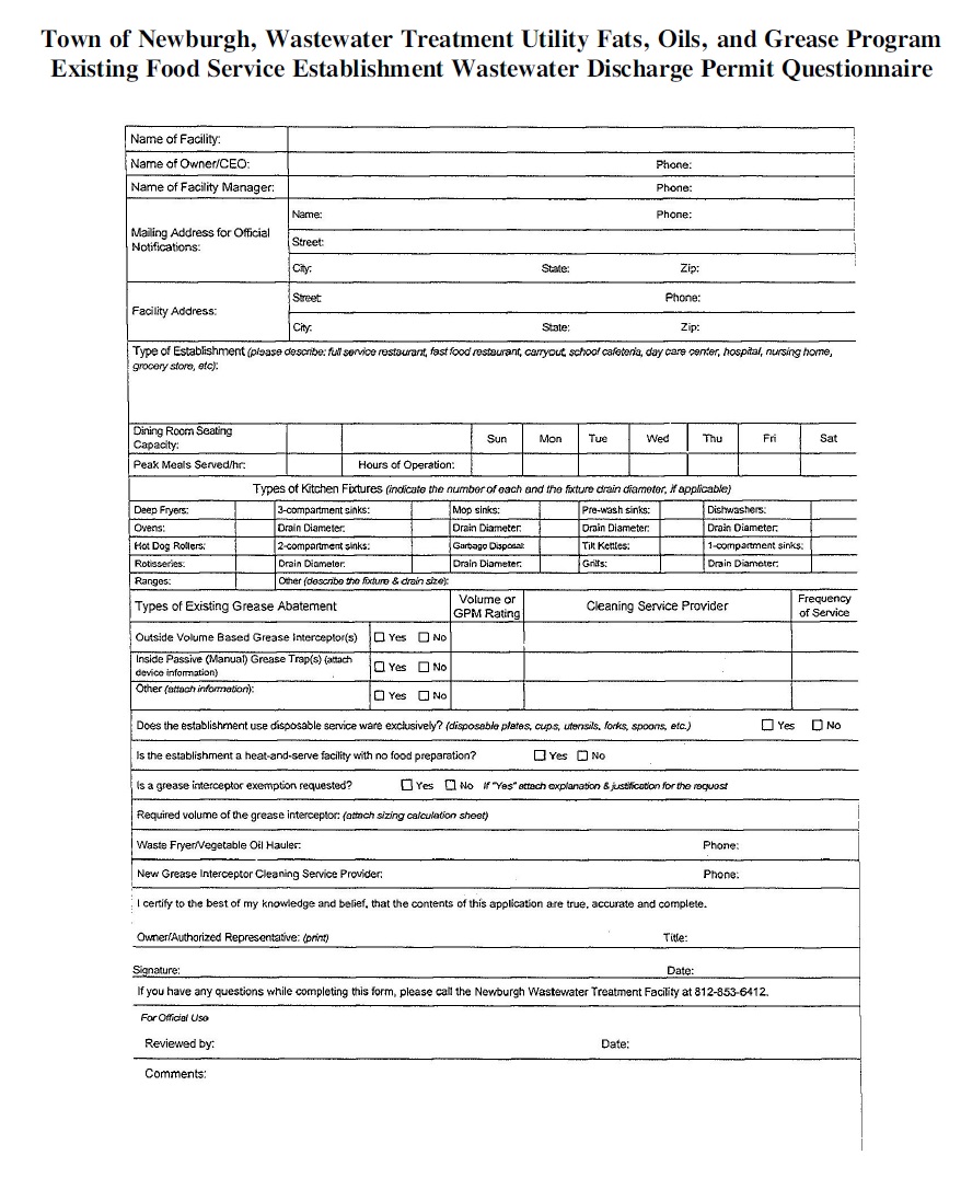
Town of Newburgh, Wastewater Treatment Utility Fats, Oils, and Grease Program
Existing Food Service Establishment Wastewater Discharge Permit Questionnaire
Existing Food Service Establishment Wastewater Discharge Permit Questionnaire
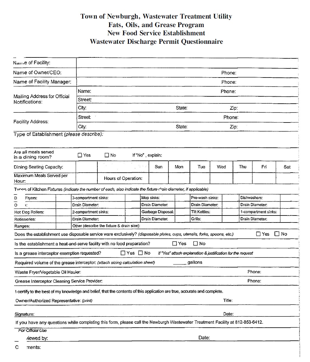
Town of Newburgh, Wastewater Treatment Utility
Fats, Oils, and Grease Program
New Food Service Establishment
Wastewater Discharge Permit Questionnaire
Fats, Oils, and Grease Program
New Food Service Establishment
Wastewater Discharge Permit Questionnaire
(Ord. 2012-20, passed 8-22-2012)
For the purpose of this chapter, the following definitions shall apply unless the context clearly indicates or requires a different meaning.
CHANGE OF USE. Conversion of an existing structure not previously meeting the definition of an establishment.
ESTABLISHMENT. The customer of the authority as described in Appendix A engaging in any of the following:
(1) Commercial food preparation and food service establishment, including, but not limited to, bakeries, butcher shops, cafés, clubhouses, commercial kitchens, delicatessens, fat rendering plants, ice cream parlors, hospitals, meat packing plants, restaurants, schools, slaughterhouses, soap factories and similar establishments, especially where meat, poultry, seafood, dairy products or fried foods are prepared or served;
(2) All shopping centers with food processing establishments and/or food courts; and
(3) All new areas of intensified dwelling, including, but not limited to: adult day care establishments, assisted living establishments, convalescent homes, day nursing and childcare establishments in which food preparation occurs, hotels/motels in which there is a commercial food preparation service, nursing homes, retirement and life care communities and homes, and truck stops with commercial food service.
EXISTING. Prior to the effective date of the FOG policy.
EXPANDED. Establishment modifications that add seating capacity or increases the number of fixtures in the kitchen area.
NEW CONSTRUCTION. Any establishment constructed after the effective date of the FOG policy
RENOVATED. Modifications sufficient to require issuance of a building permit from the locality in which the establishment is situated.
WHOLESALERS OR COMMERCIAL KITCHENS. Establishments that meet the requirements of Appendix A but do not have retail sales.
(Ord. 2012-20, passed 8-22-2012)
Loading...