You are viewing an archived code
14E-6-600 Electric signs and outline lighting.
14E-6-604 Manufactured wiring systems.
14E-6-605 Office furnishings.
14E-6-610 Cranes and hoists.
14E-6-620 Elevators, dumbwaiters, escalators, moving walks, platform lifts, and stairway chairlifts.
14E-6-625 Electric vehicle charging systems.
14E-6-626 Electrified truck parking spaces.
14E-6-630 Electric welders.
14E-6-640 Audio signal processing, amplification, and reproduction equipment.
14E-6-645 Information technology equipment.
14E-6-646 Modular data centers.
14E-6-647 Sensitive electronic equipment.
14E-6-650 Pipe organs.
14E-6-660 X-ray equipment.
14E-6-665 Induction and dielectric heating equipment.
14E-6-668 Electrolytic cells.
14E-6-669 Electroplating.
14E-6-670 Industrial machinery.
14E-6-675 Electrically driven or controlled irrigation machines.
14E-6-680 Swimming pools, fountains, and similar installation.
14E-6-682 Natural and artificially made bodies of water.
14E-6-685 Integrated electrical systems.
14E-6-690 Solar photovoltaic (PV) systems.
14E-6-691 Large-scale photovoltaic (PV) electric power production facility.
14E-6-692 Fuel cell systems.
14E-6-694 Wind electric systems.
14E-6-695 Fire pumps.
The provisions of Article 600 of NFPA 70 are adopted by reference with the following modifications:
1. Revise section 600.3 by adding new subsection (C) to read:
“Existing signs. Unlisted signs constructed or erected prior to February 7, 2002, shall comply with Chapter 14-36 of the Chicago Building Code, 1999 edition.”
2. Revise subsection 600.9(A) to read:
“Vehicles. Sign or outline lighting system equipment shall be at least 4.9 m (16 ft) above areas accessible to vehicles unless protected from physical damage.
Informational Note: See Chapter 13-20, Article XIII, of the Chicago Building Code.”
3. Insert new section 600.25 to read:
“Connections. Where signs are connected to previously installed branch circuits, the electrical contractor connecting the sign will be held responsible for the condition of the branch circuit. Connections shall not be made unless the branch circuit referred to is of sufficient capacity, in good condition, and in compliance with this Code. Signs may be connected to existing interior lighting circuits (except circuits feeding show windows) provided the combined load on the circuit does not exceed 1440 volt-amperes.
All outside wiring for signs shall be installed in rigid metal conduit, intermediate metal conduit, or electrical metallic tubing which shall be made waterproof; provided, however, for swinging signs the conduit or electrical metallic tubing shall terminate at the level of the crane within 914 mm (3 ft) of the sign and flexible conduit or other approved means shall be used to complete the connection. The flexible conduit shall have a drip loop and be arranged as not to bring moisture into the sign.
Sign branch circuits shall be installed so that the load connected shall in no case be more than 80% of the 15- or 20-ampere branch circuit overcurrent protective device.
Branch circuit conductors for each section of attraction board signs shall be routed to the distributing center of the section in rigid metal conduit, intermediate metal conduit or electrical metallic tubing.”
4. Insert new section 600.26 to read:
“Floodlights, Spotlights, and Flashing Lights. No floodlight or spotlight shall be installed in or on any sign in such a manner as to be detrimental to automobile or street traffic. The use of the colors, green, red, or amber is restricted to those signs where the use of such colors does not create a traffic hazard. Under no conditions shall flashing lights be used on a sign where they can be construed as traffic regulation or judged to be distracting to motor vehicle traffic.”
5. Insert new section 600.27 to read:
“Detailed Drawings. Detailed drawings shall be submitted with all sign permit applications. Each drawing shall contain the following information:
(1) Test laboratory listing number
(2) Manufacturers name or trademark
(3) Size in feet and inches
(4) Weight in pounds
(5) Volt-ampere load
(6) Branch circuit(s) required
(7) Scaled graphical drawing of sign
(8) Elevation showing the location of sign
(9) Engineered drawing number (where required in Section 600.28)
Informational Note: See Chapter 13-20, Article XIII, of the Chicago Building Code.”
6. Insert new section 600.28 to read:
“Engineered Drawings Required. Drawings prepared by an architect or structural engineer, licensed to practice in the State of Illinois, and bearing the seal of the architect or engineer are required for and shall be presented with the applications for permits for the erection or alteration of signs which fall into the following categories:
(1) Signs requiring a roof structure which extends more than 3.66 m (12 ft) from the roof to the top of the structure
(2) Signs requiring a roof structure if any face of the sign exceeds 5.57 m2 (60 ft2) in area
(3) Signs held by diverging guys or supports at angles less than 45 degrees with the sign (4) signs which exceed 91 kg (200 lb) in weight
(5) Projecting signs with any face which exceeds 9.3 m2 (100 ft2) in area
(6) Projecting signs having more than 50% of the vertical dimension of the sign above the roof line and having any face that exceeds 5.57 m2 (60 ft2) in area
(7) Projecting signs supported by roof structures
(8) Signs erected entirely above the roof of a building
(9) Signs supported from the ground by independent structure(s) with a top which is more than 7.32 m (24 ft) above the level of the adjoining street or surrounding grade
(10) Installation of new sign boxes or channel letters
(11) Exterior signs not made of a solid material or substance, including but not limited to paper, fabric, cloth, vinyl or similar flexible material or substance which (i) exceed 9.3 m2(100 ft2) in area or which are 7.32 m (24 ft) or more above grade and (ii) are secured to a building by means of brackets, channels, cables, hooks, nails, screws, straps, cords or other means other than a painted wall sign
(12) Where, in the opinion of the Building Department, the erection or alteration of a sign poses an unusual hazard or is not covered by this Code.”
7. Insert new sections 600.43 through 600.50 to read:
“600.43 Switches on Doors. Doors or covers giving access to uninsulated parts of signs, or outline lighting systems exceeding 600 volts nominal, and accessible to the general public, shall either be provided with interlock switches which, on the opening of the doors or covers, disconnect the primary circuit, or shall be so fastened that the use of other than ordinary tools will be necessary to open them.
600.44 Fixed Outline Lighting and Skeleton- Type Signs for Interior Use.
(A) Tube Support. Gas tubing shall be supported independently of the conductors by means of insulators of noncombustible, non-absorptive materials such as glass, or porcelain or by suspensions from suitable wires or chains.
(B) Transformers. Transformers shall be installed in metal enclosures and as near as practicable to the gas tubing system.
(C) Supply Conductors. The supply conductors for the transformers shall be enclosed in grounded metal raceway.
(D) High-Tension Conductors. High-tension conductors shall be insulated for the voltage of the circuit and shall be enclosed in an approved raceway.
Exception: Conductors not exceeding 1.22 m (4 ft) in length between as tubing and adjacent metal enclosures shall be permitted to be enclosed in continuous glass or other insulating sleeves.
600.45 Window-Type Gas Tube Sign for Show Windows and Interior Use. This section shall apply to the installation and use of window-type gas tube signs.
(A) Location. Window gas tube signs shall be for indoor use only.
(B) Transformer. The transformer shall be in a metal enclosure.
(C) Supply Conductors. Supply conductors shall consist of hard or extra-hard usage-type cord containing an equipment grounding conductor. The cord shall not exceed 1.8 m (6 ft) in length.
(D) High-Voltage Conductors. High-voltage conductors shall be as short as practicable, but not more than 1.8 m (6 ft) long and shall be located where not subject to mechanical injury, and shall be insulated for the voltage of the circuit and be protected by continuous glass or other insulating sleeves or tubing.
(E) Grounding. Transformers and attached noncurrent-carrying metal parts shall be grounded in accordance with Article 250.
(F) Support. Window-type indoor signs shall be held in place by not more than two open hooks attached to the transformer case.
(G) Permit. Window-type indoor signs shall be installed only under the authority of a permit issued to an electrical contractor.
600.46 Supports. Any sign or device covered by Article 600 Part II shall be supported by approved fastening means as described in other sections of this Code.
600.47 Receptacles. No receptacles shall be installed in any sign or device covered by this section of the chapter.
600.48 Modular Signs. Where a sign is made up of several pieces the wiring to and between such pieces shall be enclosed in a metal raceway unless specifically approved by special permission.
600.49 Length of Cord. Where flexible cord is used as the method of supplying current to any device or sign covered by this section of the chapter, such cord shall not exceed 1.8 m (6 ft) in length. All such cords shall be approved three conductors and shall be equipped with a ground-type plug.
600.50 Voltage. In no case shall primary voltage to any sign or device covered by Article 600 Part II exceed 150 volts between conductors.”
8. Insert new parts III through IV to read:
“Part III. 600 Volts, Nominal, or Less
600.60 Installation of Conductors.
(A) Wiring Method. Conductors shall be installed in rigid or flexible metal conduit, intermediate metal conduit, electrical metallic tubing, mineral-insulated metal-sheathed cable, and metal poles complying with all requirements of 410.30(B). Aerial feeders to signs shall not be permitted.
(B) Insulation and Size. Conductors shall be of a type listed for the purpose and shall not be smaller than 14 AWG.
Exception No. 1: Conductors not smaller than 18 AWG of a type listed in Table 402.3 shall be permitted:
(a) As short leads permanently attached to lampholders or electric-discharge ballasts.
(b) As leads not more than 2.44 m (8 ft) long permanently attached to electric-discharge lampholders or electric-discharge ballasts if the leads are enclosed in wiring channels.
(c) For signs with multiple incandescent lamps requiring one conductor from a control to one or more lamps whose total load does not exceed 250 watts, if in an approve cable assembly of two or more conductors.
Exception No. 2: Conductors not smaller than 20 AWG shall be permitted as short leads permanently attached to synchronous motors.
(C) Exposed to Weather. Conductors in rigid conduit, electrical metallic tubing, flexible metal conduit, or in metal trough, raceways, or enclosures, exposed to the weather shall be of a type listed in 310.10(C).
(D) Number of Conductors in Raceway. The number of conductors in a raceway for sign fixtures shall be in accordance with Article 900.
(E) Conductors Soldered to Terminals. Where the conductors are fastened to lampholders other than of the pin type, they shall be soldered to the terminals or made with wire connectors, and the exposed parts of conductors and terminals shall be treated to prevent corrosion. Where the conductors are fastened to pin-type lampholders that protect the terminals from the entrance of water and that have been found acceptable for sign use, the conductors shall be of the stranded type but shall not be required to be soldered to the terminals.
Part IV. Hanging Flat and Projecting Signs
600.70 Support.
(A) Flat Signs. Flat signs shall be anchored below roof line except that additional support other than chain may be provided over parapet to roof.
(B) Projecting Signs. Projecting signs exceeding 9.3 m2 (100 ft2) in area of one face shall be rigidly hung on beams. Separate projecting signs so hung as to appear as one sign shall be rigidly hung on beams if the total area of all faces on one side of the sign exceeds 9.3 m2 (100 ft2).
600.71 Bracing.
(A) Chain, Side Guys, and Rigid Brace Supports. All projecting signs shall have standard chain supports and fastenings to the building as shown in Table 600.71(A). Fastenings shall be so installed that attached supports or guys make an angle of 45° or greater with the sign. Where machine or lag screws enter strong structures, anchorage will be considered as equivalent to bolt throughout the wall. Expansion bolts shall be not less than 10 mm (3/8 in.) in diameter and shall enter through brick or stone walls not less than 64 mm (2-1/2 in.). Lag bolts in solid woodwork shall be not less than 10 mm (3/8 in.) in diameter and shall enter woodwork not less than 76 mm (3 in.).
Table 600.71(A) Support Chains
Weight of Sign (lb) | Number of Chains | Trade Size of Chains | Fastening to Wall |
Up to 75 | 1 | 4/0 | Two expansion bolts per chain |
76 to 150 | 2 | 4/0 | Two expansion bolts per chain |
151 to 400 | 2 | 8/0 | One expansion bolts per chain |
401 to 1,000 | 2 | 10/0 | One expansion bolts per chain |
(B) Supporting Chain. No supporting chain shall be attached back of the center of gravity of the sign, except in the case of the rear supports of vertical signs.
(C) Lift Chain. Each lift chain shall be capable of carrying the sign alone. Fastenings for signs, supports or guys shall not be attached to, or rest on, parapet walls and shall be not less than 203 mm (8 in.) from any corner of the building.
(D) Projecting Signs. All projecting signs shall have standard chain side guys or rigid brace supports as shown in Tables 600.71(D)(1), (2), or (3).
Table 600.71(D)(1) Number and Size of Chain Guys for Each Side of Guy
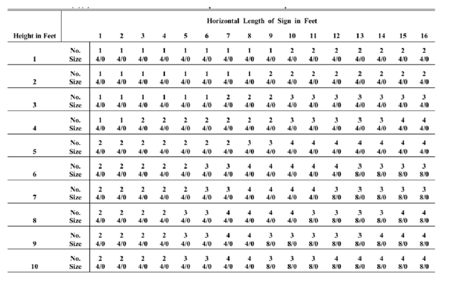
Table 600.71(D)(2) Capacity in Square Feet of Sign Surface for Pipe Braces
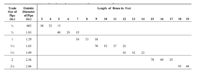
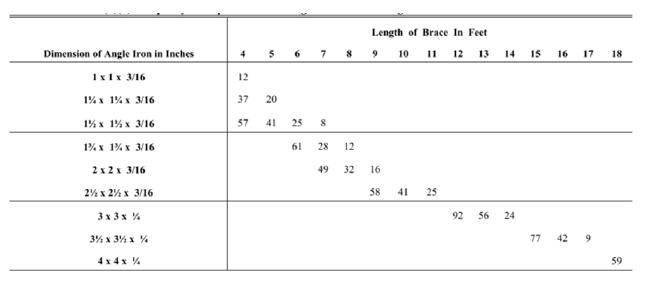
Table 600.71(D)(3) Capacity in Square Feet of Sign Surface for Angle Iron Braces
Note 1. There shall not be more than 40 ft2 to one brace.
Note 2. Pipe braces shall not have joints near center.
Note 3. The ends of the pipe shall be closed by welding or by the use of an approved fitting.
(E) Hinged Projecting Signs. Projecting signs with chain or rigid pipe side guys shall be hinged at the building so that, should the sign swing on account of loosening of the side guys, no undue strain will be placed on the supporting bolts. Where the length of the hanger iron projecting from the sign frame is of a length that will not permit hinging due to the interference of the sign drum with the supporting wall said wall connections shall be made by means of two anchor bolts in the wall for each hanger iron, and the wall plates shall be fastened with not less than two bolts to the iron frame of the sign.
(F) Side Guy Chain. Each chain used for the support of for the side guy of sign shall have an independent attachment to the building or supporting structure, and shall make an angle of 45° or greater with the sign.
(G) Supporting Chains. Where supporting chains are attached to bolts through the wall such bolts shall be not less than 16 mm (5/8 in.) in diameter. The bolt shall be anchored by a washer plate of not less than 610 mm2(24 in.2) of surface and of not less than 3.2 mm (1/8 in.) thick.
(H) Window Frames or Sills. Chains or signs shall not be fastened to window frames or sills.
(I) Turnbuckle. A turnbuckle shall be provided for all supporting chains and side guys. Turnbuckles shall have a breaking strength equivalent to that of the chain to which they are attached and shall be not less than 4.8 mm (3/16 in.).
(J) Split Links. Split links used for connections of chains shall be of standard design and shall have a breaking strength at least equivalent to that of the chain to which they are attached.
(K) Corrosion Protection. All chains, turnbuckles, split links, bolts and screws, and all other devices which support or form part of the support of a sign shall be galvanized or otherwise suitably protected from corrosion in some approved manner.
(L) Saddling. Where necessary to use a saddle for the fastening of a building iron, rigid construction shall be used. Chains will not be approved.
(M) Machine Screws. Machine screws in iron fronts shall be not less than 1/2 in. in diameter and shall pass through iron work.
(N) Wooden Bays. Projecting signs, lift chains or guys shall not be attached to wooden bays.
600.80Swinging Signs. Swinging signs shall be supported by a pipe crane, or the equivalent, as shown in Table 600.80.
Swinging signs having a length of more than 2.44 m (8 ft) shall have not less than three hanging irons. Not less than two bolts shall be used to fasten strap to hanging iron. All cranes shall be further supported by an additional lift chain not more than 610 mm (2 ft) from building. No crane shall be erected higher than 8.53 m (28 ft) above the public way.
Table 600.80 Swinging Sign Supports
Weight | Pipe Size |
0 – 75 lb | 1 in. |
76 – 150 lb | 1-1/4 in. |
151 – 300 lb | 1-1/2 in. |
301 – 450 lb | 2 in. |
451 – 1,000 lb | 2-1/2 in. |
600.90Supporting Poles or Posts. Supports for signs shall be either steel beams, round steel pipe sections or square steel (hollow) sections.
(A) Single Supporting Member. Signs which have a single supporting member shall be restricted to round steel pipe sections or square steel sections. The sections may consist of a fabricated and welded assembly, provided the welding is performed by a certified welder.
(B) Minimum Support. The minimum requirements for the support of signs shall be based upon a combined torsional and bending moment for a wind pressure of 1440 Pa (30 psf) and sign weight involved, using a maximum fiber stress of 138,000 kPa (20,000 psi).
(C) Drawing. A sketch, or engineer's drawings where required by this Code, shall accompany each permit application. The sketch or drawing shall show complete and detailed information of the construction and installation of the sign.
(D) Design Values. The values listed in Tables 600.90(A) and (B) are minimum and are based upon an elevation of not more than 3.7 m (12 ft) above the surrounding grade or ground level to the bottom of the sign. The dimensions of the sign shall be such that a ratio between the two dimensions of the sign shall not exceed two to one. The distance between the center line of the support and the sign edge shall not exceed 750 mm (30 in.) for projecting signs. Deviation from the provisions of this section may be permitted by special permission, provided drawings are submitted from a structural engineer licensed to practice in the State of Illinois. Such drawings must attest to the fact that the proposed installation is equal to or greater than the standard required by this section.
Table 600.90(D)(1) Minimum Support Size for Projecting Signs
Area of One Face in ft2 | Round Pipe in Inches | Square Tubular Section in Inches |
Area of One Face in ft2 | Round Pipe in Inches | Square Tubular Section in Inches |
Up to 10 | 4 (.237 wall) | 3 x 3 x 1/4 |
11 to 20 | 6 (.280 wall) | 4 x 4 x 3/16 |
21 to 30 | 8 (.250 wall) | 5 x 5 x 1/4 |
31 to 40 | 8 (.250 wall) | 6 x 6 x 1/4 |
41 to 50 | 8 (.322 wall) | 7 x 7 x 1/4 |
51 to 60 | 10 (.250 wall) | 8 x 8 x 1/4 |
61 to 70 | 10 (.365 wall) | 8 x 8 x 1/4 |
71 to 75 | 10 (.365 wall) | 10 x 10 x 1/4 |
Table 600.90(D)(2) Minimum Support Size for Concentrically Mounted Signs
Area of One Face in ft2 | Round Pipe in Inches | Square Tubular Section in Inches |
Area of One Face in ft2 | Round Pipe in Inches | Square Tubular Section in Inches |
Up to 10 | 4 (.237 wall) | 3 x 3 x 1/4 |
11 to 20 | 5 (.258 wall) | 4 x 4 x 3/16 |
21 to 30 | 6 (.280 wall) | 5 x 5 x 1/4 |
31 to 40 | 8 (.280 wall) | 6 x 6 x 1/4 |
41 to 50 | 8 (.322 wall) | 7 x 7 x 1/4 |
51 to 60 | 10 (.250 wall) | 8 x 8 x 1/4 |
61 to 70 | 10 (.368 wall) | 8 x 8 x 1/4 |
71 to 75 | 10 (.365 wall) | 8 x 8 x 1/4 |
600.100 Obstructions
(A) Obstructions. Signs shall not obstruct or be attached to any part of a fire escape, and where a sign is hung near a fire escape, it shall be arranged to swing away from such fire escape.
(B) Clearance from Conductors. Signs shall be installed so that a clearance of not less than 900 mm (3 ft) is maintained between any wire of a high potential circuit and the sign, sign support, or sign guy. Similar clearance of not less than 300 mm (12 in.) shall be maintained between any other municipal or public utility wire. Sign hangers shall make arrangements to have wires rerouted when necessary before the sign is hung.
(C) Windows. Signs covering windows used for required natural light or required natural ventilation will not be approved without special permission.
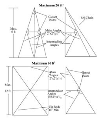
600.110Roof Structures. Roof structures shall be installed when the required 45° angle of the lift chain cannot be made of the building wall. Roof structures less than 3.7 m (12 ft) shall conform to Figure 600.110.
Where the height does not exceed 3.7 m (12 ft) for signs up to 3.7 m2 (40 ft²) in area the main angles shall be 2" x 2" x 1/4" and the intermediate angles shall be 1-1/2" x 1-1/2" x 3/16"; for signs over 3.7 m2 (40 ft2) in area the main angles shall be 2-1/2" x 2-1/2" x 1/4" and the intermediate angles shall be 2" x 2"x 1/4". Roof structures over 3.7 m (12 ft) high or more than 5.6 m2 (60 ft2) shall have engineer's drawings required by 600.28.
Figure 600.110 Roof Structures
600.120 Catwalks and Ladders
(A) Catwalks. Catwalks for maintenance purposes on signs and sign structures shall be constructed of metal.
(B) Ladder on Sign Structures. Ladder on sign structures shall be at least 375 mm (15 in.) wide. Ladders on signs shall be metal and shall be not less than 250 mm (10 in.) wide. Horizontal projecting signs, the bottoms of which are more than 8.5 m (28 ft) above the public way, shall be provided with catwalks and handrails.
(C) Horizontal Flat Signs. Horizontal flat signs, the bottoms of which are more than 8.5 m (28 ft) above the public way shall be provided with catwalks and handrails unless signs can be maintained by means other than ladders supported from the way.
(D) Vertical Signs. Vertical signs, the bottoms of which are more than 8.5 m (28 ft) above the public way, or with a vertical dimension of more than 7.5 m (25 ft), shall have ladders the full vertical distance of the sign. In addition, all signs in the above category which are more than 1.2 m (4 ft) wide shall be provided with a steel structure at the top of the sign for maintenance purposes.”
(Added Coun. J. 9-6-17, p. 55278, Art. I, § 1)
The provisions of Article 605 of NFPA 70 are adopted by reference with the following modifications:
1. Revise the first clause and subsequent exception of section 605.3 to read:
“General. Wiring systems shall be identified as suitable for providing power for lighting accessories and utilization equipment used within office furnishings. A wired partition may extend from floor to ceiling but shall not penetrate the ceiling. All internal wiring to the partitions shall be installed with a recognized wiring method. Where tight turns are encountered, 3/8” or 1/2” trade size flexible metal conduit may be installed. Where flexible metallic conduit is installed, a separate green grounding conductor of the wire type, shall be installed in the flexible metal conduit, and shall also bond all of the metal boxes together.
Exception: Where bends of a radius less than that available with 3/8” or 1/2” trade size flexible metal conduit, listed and labeled super flexible metallic conduit with nylon jackets conductors maybe used.”
2. Revise the first paragraph of section 605.5 to read:
“The electrical connection between office furnishings shall be a flexible metal conduit identified for use with office furnishings or, for office furnishings meeting the requirements of 605.9, shall be permitted to be installed using flexible cord provided that all of the following conditions are met:”
3. Revise the title and first paragraph of section 605.6 to read:
“Lighting Equipment and Utilization Equipment. Lighting equipment and utilization equipment shall be listed, labeled, and identified for use with office furnishings and shall comply with 605.6(A), (B) and (C).”
4. Revise section 605.7 to read:
“Office Furnishings. Office furnishings other than those meeting the requirements of 605.9 shall be permanently connected to the building electrical system by one of the wiring methods of Chapter 3.”
5. Delete section 605.8.
6. Revise the title and first paragraph of section 605.9 to read:
“Office Furnishings, Cord- and Plug-Connected. Individual office furnishings or groups of individual office furnishings that are electrically connected, are mechanically contiguous, and do not exceed 9.0 m (30 ft) when assembled, and which are either sufficiently lightweight or equipped with features such as wheels to readily allow repositioning by users, shall be permitted to be connected to the building electrical system by a single flexible cord and plug, provided that the conditions of 605.9(A) through (D) are met.”
(Added Coun. J. 9-6-17, p. 55278, Art. I, § 1; Amend Coun. J. 1-23-19, p. 94952, Art. I, § 23)
The provisions of Article 610 of NFPA 70 are adopted by reference with the following modification:
1. Revise section 610.11 to read:
“Wiring Method. Conductors shall be enclosed in metal raceways, or be Type MC cable or Type MI cable unless otherwise permitted or required in 610.11(A) through (E).
(A) Contact Conductor. Contact conductors shall not be required to be enclosed in raceways.
(B) Exposed Conductors. Short lengths of exposed conductors at resistors, collectors, and other equipment shall not be required to be enclosed in raceways.
(C) Flexible Connections to Motors and Similar Equipment. Where flexible connections are necessary, flexible stranded conductors shall be used. Conductors shall be in flexible metal conduit, liquidtight flexible metal conduit, multiconductor cable, or an approved metallic flexible raceway.
(D) Pushbutton Station Multiconductor Cable. Where multiconductor cable is used with a suspended pushbutton station, the station shall be supported in some satisfactory manner that protects the electrical conductors against strain.
(E) Flexibility to Moving Parts. Where flexibility is required for power or control to moving parts, listed festoon cable or a cord suitable for the purpose shall be permitted, provided the following apply:
(1) Suitable strain relief and protection from physical damage is provided.
(2) In Class I, Division 2 locations, the cord is approved for extra-hard usage.”
(Added Coun. J. 9-6-17, p. 55278, Art. I, § 1)
The provisions of Article 620 of NFPA 70 are adopted by reference with the following modification:
1. Revise section 620.21 to read:
“Wiring Methods. Conductors and optical fibers located in hoistways, in escalator and moving walk wellways, in platform lifts, stairway chairlift runways, machinery spaces, control spaces, in or on cars, in machine rooms and control rooms, not including the traveling cables connecting the car or counterweight and hoistway wiring, shall be installed in rigid metal conduit, intermediate metal conduit, electrical metallic tubing, or metal wireways, or shall be Type MI cable unless otherwise permitted in 620.21(A) through (C).
(A) Elevators.
(1) Hoistways and Pits.
(a) Cables used in Class 2 power-limited circuits shall be permitted, provided the cables are supported and protected from physical damage and are of a jacketed and flame-retardant type.
(b) Flexible cords and cables that are components of listed equipment and used in circuits operating at 30 volts rms or less or 42 volts dc or less shall be permitted in lengths not to exceed 1.8 m (6 ft) provided the cords and cables are supported and protected from physical damage and are of a jacketed and flame-retardant type.
(c) The following wiring methods shall be permitted in the hoistway in lengths not to exceed 1.8 m (6 ft):
(1) Flexible metal conduit
(2) Liquidtight flexible metal conduit
(3) Flexible cords and cables, or conductors grouped together and taped or corded, shall be permitted to be installed without a raceway. They shall be located to be protected from physical damage and shall be of a flame-retardant type and shall be part of the following:
a. Listed equipment
b. A driving machine, or
c. A driving machine brake
Exception to 620.21(A)(1)(c)(1), (2), and (3): The conduit length shall not be required to be limited between risers and limit switches, interlocks, operating buttons, and similar devices.
(d) A sump pump or oil recovery pump located in the pit shall be permitted to be cord connected. The cord shall be a hard usage oil-resistant type, of a length not to exceed 1.83 m (6 ft), and shall be located to be protected from physical damage.
(2) Cars.
(a) Flexible metal conduit, and liquidtight flexible metal conduit of metric designator 12 (trade size 3/8), or larger, not exceeding 1.8 m (6 ft) in length, shall be permitted on cars where so located as to be free from oil and if securely fastened in place.
(b) Hard-service cords and junior hard- service cords that conform to the requirements of Article 400 (Table 400.4) shall be permitted as flexible connections between the fixed wiring on the car and devices on the car doors or gates. Hard-service cords only shall be permitted as flexible connections for the top-of-car operating device or the car-top work light. Devices or luminaires shall be grounded by means of an equipment grounding conductor run with the circuit conductors. Cables with smaller conductors and other types and thicknesses of insulation and jackets shall be permitted as flexible connections between the fixed wiring on the car and devices on the car doors or gates, if listed for this use.
(c) Flexible cords and cables that are components of listed equipment and used in circuits operating at 30 volts rms or less or 42 volts dc or less shall be permitted in lengths not to exceed 1.8 m (6 ft) provided the cords and cables are supported and protected from physical damage and are of a jacketed and flame-retardant type.
(d) The following wiring methods shall be permitted on the car assembly in lengths not to exceed 1.8 m (6 ft):
(1) Flexible metal conduit
(2) Liquidtight flexible metal conduit
(3) Flexible cords and cables, or conductors grouped together and taped or corded, shall be permitted to be installed without a raceway. They shall be located to be protected from physical damage and shall be of a flame-retardant type and shall be part of the following:
a. Listed equipment
b. A driving machine, or
c. A driving machine brake
(3) Within Machine Rooms, Control Rooms, and Machinery Spaces and Control Spaces.
(a) Flexible metal conduit, and liquidtight flexible metal conduit of metric designator 12 (trade size 3/8) or larger, not exceeding 1.8 m (6 ft) in length, shall be permitted between control panels and machine motors, machine brakes, motor-generator sets, disconnecting means, and pumping unit motors and valves.
(b) Where motor-generators, machine motors, or pumping unit motors and valves are located adjacent to or underneath control equipment and are provided with extra-length terminal leads not exceeding 1.8 m (6 ft) in length, such leads shall be permitted to be extended to connect directly to controller terminal studs without regard to the carrying-capacity requirements of Articles 430 and 445. Auxiliary gutters shall be permitted in machine and control rooms between controllers, starters, and similar apparatus.
(c) Flexible cords and cables that are components of listed equipment and used in circuits operating at 30 volts rms or less or 42 volts dc or less shall be permitted in lengths not to exceed 1.83 m (6 ft), provided the cords and cables are supported and protected from physical damage and are of a jacketed and flame-retardant type.
(d) On existing or listed equipment, conductors shall also be permitted to be grouped together and taped or corded without being installed in a raceway. Such cable groups shall be supported at intervals not over 900 mm (3 ft) and located so as to be protected from physical damage.
(e) Flexible cords and cables in lengths not to exceed 1.8 m (6 ft) that are of a flame-retardant type and located to be protected from physical damage shall be permitted in these rooms and spaces without being installed in a raceway. They shall be part of the following:
(1) Listed equipment
(2) A driving machine, or
(3) A driving machine brake
(4) Counterweight. The following wiring methods shall be permitted on the counterweight assembly in lengths not to exceed 1.8 m (6 ft):
(1) Flexible metal conduit
(2) Liquidtight flexible metal conduit
(3) Flexible cords and cables, or conductors grouped together and taped or corded, shall be permitted to be installed without a raceway. They shall be located to be protected from physical damage, shall be of a flame-retardant type, and shall be part of the following:
a. Listed equipment
b. A driving machine, or
c. A driving machine brake
(B) Escalators.
(1) Wiring Methods. Flexible metal conduit or liquidtight flexible metal conduit shall be permitted in escalator and moving walk wellways. Flexible metal conduit or liquidtight flexible conduit of metric designator 12 (trade size 3/8) shall be permitted in lengths not in excess of 1.8 m (6 ft).
(2) Class 2 Circuit Cables. Cables used in Class 2 power-limited circuits shall be permitted to be installed within escalators and moving walkways, provided the cables are supported and protected from physical damage and are of a jacketed and flame- retardant type.
(3) Flexible Cords. Hard-service cords that conform to the requirements of Article 400 (Table 400.4) shall be permitted as flexible connections on escalators and moving walk control panels and disconnecting means where the entire control panel and disconnecting means are arranged for removal from machine spaces as permitted in 620.5.
(C) Platform Lifts and Stairway Chairlift Raceways.
(1) Wiring Methods. Flexible metal conduit or liquidtight flexible metal conduit shall be permitted in platform lifts and stairway chairlift runways and machinery spaces. Flexible metal conduit or liquidtight flexible conduit of metric designator 12 (trade size 3/8) shall be permitted in lengths not in excess of 1.8 m (6 ft).
(2) Class 2 Circuit Cables. Cables used in Class 2 power-limited circuits shall be permitted to be installed within platform lifts and stairway chairlift runways and machinery spaces, provided the cables are supported and protected from physical damage and are of a jacketed and flame-retardant type.
(3) Flexible Cords and Cables. Flexible cords and cables that are components of listed equipment and used in circuits operating at 30 volts rms or less or 42 volts dc or less shall be permitted in lengths not to exceed 1.83 m (6 ft) provided the cords and cables are supported and protected from physical damage and are of a jacketed and flame-retardant type.”
(Added Coun. J. 9-6-17, p. 55278, Art. I, § 1)
Loading...