(a) General Provisions. The following Design Criteria are summarized herein to establish practical uniform design of storm sewers for the City. These criteria cover design factors and provide guidelines for evaluation of plans and specifications by the political subdivisions having jurisdiction over the review of plans and specifications. These Design Criteria are also intended to conform to the standard drawings for storm sewers. Storm sewer design should follow these criteria and Ohio Department of Transportation Location and Design, Volume Two, Drainage Design.
(b) Storm Sewer and Inlet Grate Design. An adequate storm drainage system shall be constructed for all proposed developments. Natural drainage areas should be closely followed.
Outlets for the storm water runoff for development upstream of the proposed development must be provided. All storm sewer calculations must be submitted to the City before any approvals will be given.
Storm runoff from urban areas may constitute a large volume of flow. The rational method is the preferred method for estimating storm runoff for areas less than or equal to 100 acres. Once the runoff is determined, the Manning Formula is the preferred method to calculate the capacity of the storm sewer pipes. Storm sewer shall be designed based on the full flow capacity of all pipes being able to carry at least the runoff from a 5-year storm event.
Also, the Hydraulic Grade Line (HGL) should be checked to ensure that a 25-year storm event will not cause ponding water at catch basins and manholes.
The Rational Formula used to compute the runoff that reaches a storm sewer inlet consists of the following:
Q = CiA
Q = Peak rate of runoff in cubic feet per second (cfs)
C = A coefficient expressing the ratio of runoff to the average rainfall rate during the time of concentration
i = Intensity of rainfall, in inches per hour
A = Drainage area, in acres
Other methods for determination of peak runoff rates may be used upon approval from or by request of the City.
TABLE 6.1
RUNOFF COEFFICIENT - C
Predominant Land Use | |
Business: | |
Downtown Area | .80 |
Neighborhood Area | .70 |
Residential: | |
Single-Family Areas | .40 |
Multi-Family Areas | .60 |
Industrial: | |
Light Areas | .70 |
Heavy Areas | .80 |
Parks, Cemeteries | .30 |
Playgrounds | .35 |
Railroad Yard Areas | .35 |
Row Crops or Open Land
| .25 |
Surface Characteristics: | |
Street: | |
Asphalt | .90 |
Concrete | .90 |
Drives and Walks | .90 |
Roofs | .85 |
Lawns | |
Flat - 2% or less | .25 |
Average - 2% to 7% | .35 |
Steep - 7% or greater
| .40 |
Table 6.1
Lists values of “C” for several land uses and surface characteristics. If more than one land use is present in a particular drainage area, a composite “C” value should be computed to represent the site.
Figure 6.1
Time of Concentration Worksheet
(to be utilized when overland flow is less than 1,000 feet)
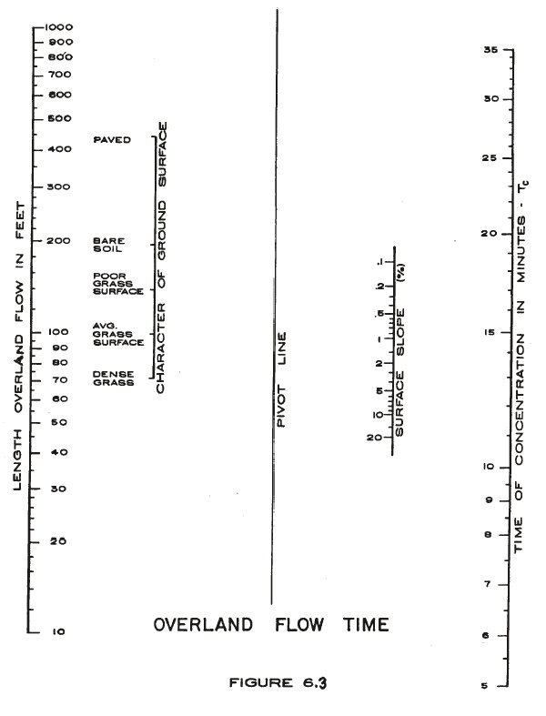 |
Figure 6.2
Time of Concentration Worksheet, Derived from TR-55
(to be utilized when overland flow is greater than 1,000 feet)
Project: By: Date:
Location: Checked: Date:
Circle one: Present Developed
Circle one: Tc Tt through subarea
NOTES: Space for as many as two segments per flow type can be used for each worksheet. Include a map, schematic, or description of flow segments.
Overland (Sheet) flow (Applicable as part of Tc computation only) Segment ID | |||||
1. Surface description: paved or unpaved........................ | |||||
2. Manning’s roughness coeff., n (See Figure 6.3)........ | |||||
3. Flow length, L (total L 300 ft for unpaved, L 100 ft for paved)........ ft | |||||
4. Two-yr 24-hr rainfall, P2..................................................in | 2.16 | 2.16 | |||
5. Land slope, s..................................................................ft/ft | |||||
0.007 (nL) 0.8 6. Tt = P2 0.5 S 0.4 Compute Tt ................... hr | + | = | |||
Shallow concentrated flow Segment ID | |||||
7. Surface description: paved or unpaved.......................................... | |||||
8. Flow length, L .............................................................................ft | |||||
9. Watercourse slope, s ...............................................................ft/ft | |||||
10. Average velocity, V unpaved = 16.1345(s) 0.5, or P paved = 2-.3282(s) 0.5 ..........ft/s | |||||
L 11. Tt = 3600 V Compute Tt............................hr | + | = | |||
Channel flow Segment ID | |||||
12. Cross sectional flow area, a ..................................................ft2 | |||||
13. Wetted perimeter, pw ..............................................................ft | |||||
a 14. Hydraulic radius, r = pw Compute r.......................................ft | |||||
15. Channel slope, s .....................................................................ft/ft | |||||
16. Manning’s roughness coeff., n...................................................... | |||||
1.49 r 2/3 s 1/2 17. V = n Compute V ......................ft/s | |||||
18. Flow length, L ..........................................................................ft | |||||
L 19. Tt = 3600 V Compute Tt.................................hr | + | = | |||
20. Watershed or subarea Tc or Tt (add Tt, in septs 6, 11 and 19) ......hr. | |||||
Figure 6.3
Surface Description | n1 Coeff. |
Smooth surfaces (concrete, asphalt, gravel, or bare soil) | 0.011 |
Fallow (no residue) | 0.05 |
Cultivated soils: Residue cover < = 20% Residue cover > = 20% | 0.06 0.17 |
Grass: Short grass prairie Dense grasses2 Bermuda grass | 0.15 0.24 0.41 |
Range (natural) | 0.13 |
Woods:3 Light underbrush Dense underbrush | 0.40 0.80 |
1 The n values are a composite of information compiled by Engman (1986). 2 Includes species such as weeping lovegrass, bluegrass, buffalo grass, blue grama grass, and native grass mixtures. 3 When selecting n, consider cover to a height of about 0.1 ft. This is the only part of the plant cover that will obstruct sheet flow. | |
Source: TR-55, Urban Hydrology for Small Watersheds, U.S. Dept. of Agriculture, Soil Conservation Service, Engineering Division, June 1986.
Table 6.2
Intensity - Duration - Frequency Table
Hours | Minutes | Return Frequency – Rainfall Intensity (in/hr) | |||||
2-yr | 5-yr | 10-yr | 25-yr | 50-yr | 100-yr | ||
.08 | 5* | 4.15 | 5.54 | 6.25 | 7.12 | 7.82 | 8.54 |
.17 | 10 | 3.35 | 4.51 | 5.08 | 5.87 | 6.20 | 6.97 |
.25 | 15 | 2.90 | 3.81 | 4.37 | 5.08 | 5.57 | 6.08 |
.33 | 20 | 2.50 | 3.29 | 3.81 | 4.46 | 4.80 | 5.36 |
.50 | 30 | 1.86 | 2.54 | 2.97 | 3.50 | 3.86 | 4.28 |
.75 | 45 | 1.40 | 1.88 | 2.20 | 2.60 | 2.88 | 3.22 |
1 | 60 | 1.12 | 1.52 | 1.78 | 2.10 | 2.34 | 2.61 |
2 | 120 | 0.68 | 0.91 | 1.08 | 1.27 | 1.42 | 1.55 |
3 | 180 | 0.50 | 0.675 | 0.80 | 0.94 | 1.05 | 1.16 |
6 | 360 | 0.30 | 0.40 | 0.48 | 0.56 | 0.62 | 0.68 |
12 | 720 | 0.16 | 0.23 | 0.27 | 0.37 | 0.36 | 0.39 |
24 | 1440 | 0.09 | 0.13 | 0.15 | 0.18 | 0.20 | 0.22 |
* Minimum Time of Concentration.
** Interpolation is acceptable to obtain values not provided in the above table.
Table 6.2
This can be used to determine values of “I” for several storm frequencies.
The Manning Formula, used to compute flow in open conduits, consists of the following:
Q = 1.486 R 2/3 S 1/2 A n |
Q = Flow in cubic feet per second (cfs)
n = Coefficient of conduit roughness (n = 0.013)
R = Hydraulic radius, ratio of flow area to wetted perimeter in feet
S = Channel or pipe slope, in feet per feet
A = Area of Cross-section of flow in square feet
The design of storm sewers in the City of Urbana shall be outlined as follows.
(a) Prepare a contour map of the drainage area including the surrounding area, drainage limits, and direction of surface flow.
(b) Divide the area into the subareas tributary to the proposed sewer inlets. These inlets should be located at reversals of road grade from negative to positive and at street intersections. A maximum distance of 300 feet between catch basins will be allowed along long street grades.
(c) Determine the acreage and imperviousness of each area.
(d) Calculate the required capacity of each inlet using the appropriate time of concentration, the tributary area and the rational method.
(e) Beginning at the highest elevation, compute the flow to be carried by each line. The time of concentration for each line other than the first in a series is the sum of the time of concentration to the inlet next upstream and the flow time in the connecting pipe. Where more than two lines meet, the time of concentration to be used for the succeeding line is the longest time in the lines meeting. Each line will thus require calculation of time of concentration, tributary area (all upstream areas), and flow.
(f) Select tentative pipe sizes and grades using the Manning Formula. Each line must be selected in order since the time of concentration for subsequent lines will be dependent upon the time of flow in all upstream lines.
(g) Minimum cover requirements specified by ASTM specifications must be met.
(h) Figure 6.4, Computation for Storm Sewer Design, may be used for storm sewer calculation.
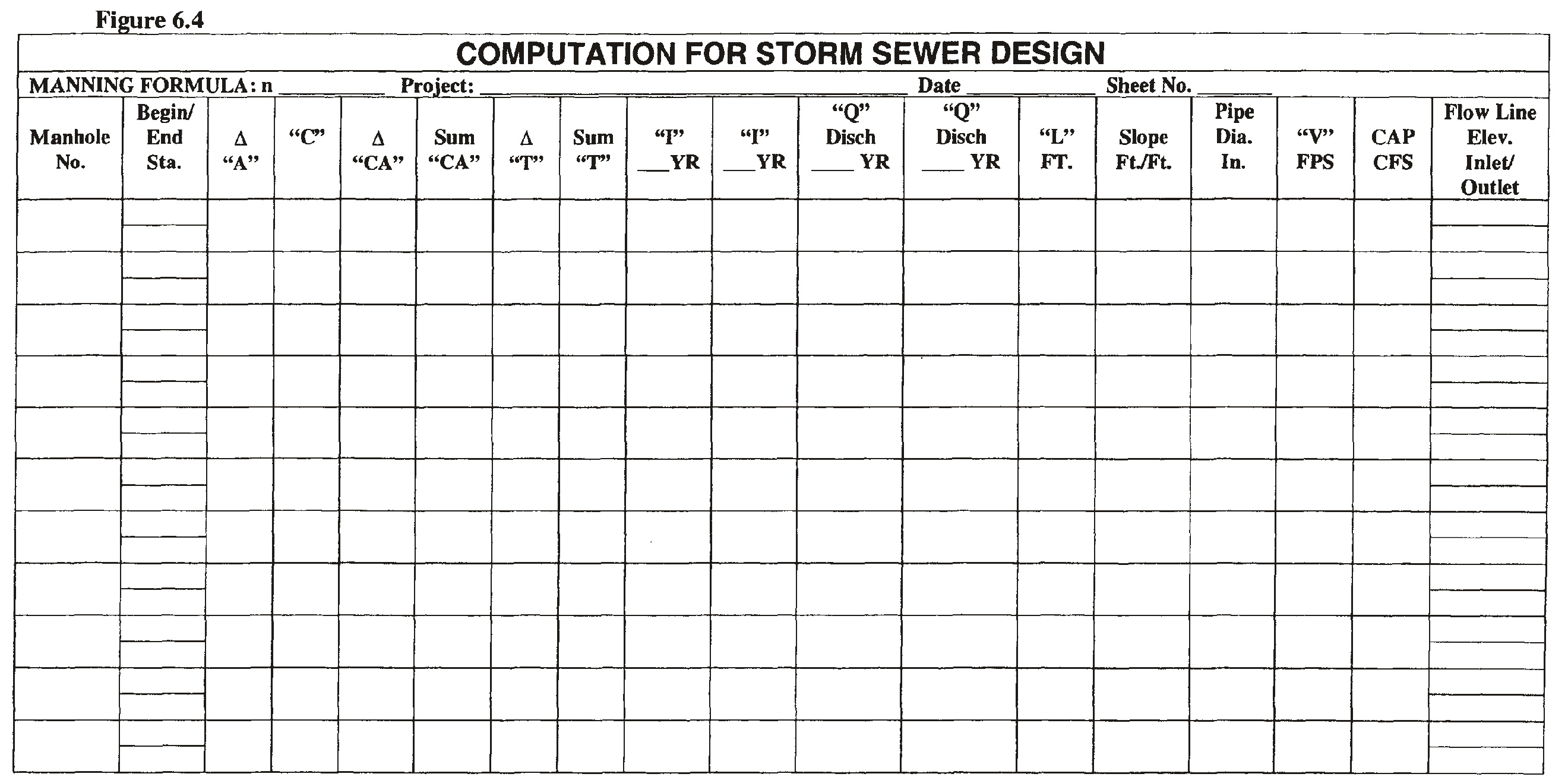 |
(c) Minimum Diameter. The minimum diameter of storm sewer pipe shall be 12 inches. The diameter shall be increased as necessary according to the design analysis.
(d) Minimum Cover. The minimum cover over storm sewer pipe shall be 2 feet unless otherwise approved by the City Engineer. Cover is measured from the top of pipe to the finished grade directly above the pipe.
(e) Minimum Slope. The minimum recommended slope for storm sewers shall be 0.10 foot per 100 feet, unless a greater slope is required to obtain the minimum mean velocity. Culverts may be installed on flatter grades as approved by the City Engineer.
(f) Minimum Velocity. The absolute minimum mean velocity for all storm sewers shall be 2.0 feet per second when flowing full based on Manning’s Formula using an “n” value of 0.013. Use of other ”n” values will be considered if deemed justifiable on the basis of extensive field data. The desirable minimum velocity is 3.0 feet per second based on the same criteria.
(g) Maximum Velocity. The maximum velocity of all storm sewers shall be 10 feet per second. If the velocity is greater than 10 feet per second, provisions should be made to protect against displacement and erosion of the pipe.
(h) Maximum Headwater. The maximum allowable headwater depth for culverts shall be 2 feet below pavement surfaces and/or finish floor elevations.
(i) Manholes. Manholes shall be installed at the end of each line, at all changes in grade, size, alignment, and at all pipe intersections. Manholes shall be installed at distances not greater than 400 feet. Intervals of more than 400 feet may be approved in sewers 42 inches and larger. Manholes may be either poured in place or precast concrete. Concrete construction shall conform to ASTM C-478.
The flow channel through manholes should be made to conform in shape, slope, and smoothness to that of the sewers.
All manhole covers shall be adjusted to grade by the use of no more than 12 inches of precast adjusting collars.
Manholes shall be consistent with those shown in the standard drawings.
(j) Manhole Minimum Diameter. Manholes shall be constructed large enough to allow access to all sewers. The minimum diameter of manholes shall be 48 inches. Where large sewers require the use of manholes diameters greater than 48 inches, the manhole shall be returned to the 48-inch diameter as soon as practical above the sewer crown. Manhole openings of 24 inches or larger are recommended for easy access with safety equipment and to facilitate maintenance.
(k) Catch Basins. Curb inlets shall be placed at all low points, points of change to a flatter street grade, the dead end of descending streets, and at the Point of Curvature and Point of Tangency of all intersection radius curves where the street grade descends toward the radius curve and at all intersections. The basis for the design and spacing of curb inlets shall conform to the Bureau of Roads Hydraulic Engineering Circular No. 12, “Drainage of Highway Pavements”.
Under normal conditions, curb inlets shall be placed on both sides of the street at intervals indicated by the street grade. Approximate spacing ranges from 150 feet to 300 feet maximum under normal conditions for the spread of flow-in gutters.
Catch basins not placed in the street shall be selected and placed so that they blend with the surroundings and not appear unsightly.
Curb inlets shall be placed on the property lines if at all possible.
Catch basin types shall be consistent with the types shown in the standard drawings.
(l) Basis of Culvert Design. The basis of design for highway culverts shall be the Bureau of Roads Hydraulic Engineering Circular No. 5, “Hydraulic Charts for the Selection of Highway Culverts”. Design shall be based on a 25-year storm for full flow capacity and an overtopping capacity of at least a 100-year storm.
(m) Open Drainage Ditches. The basis of design for drainage ditches shall be the Manning Formula, as defined in Section 1163.02
. Figure 6.2 may be used to determine the value of “n”, Manning’s Roughness Coefficient, to be used in the calculations. These calculations of open ditch capacity should be provided to the reviewing agency along with the construction drawings.
TABLE 6.3
CHANNEL MATERIAL | n |
Vitrified clay |
0.014 |
Cast iron pipe |
0.015 |
Smooth earth |
0.018 |
Firm gravel |
0.023 |
Corrugated metal pipe |
0.022 |
Natural channels in good condition |
0.025 |
Natural channels with stones and weeds |
0.035 |
Very poor natural channels |
0.060 |
(n) Channel Protection. Channel protection material shall be placed at pipe outlets and other areas of high velocity flow to prevent erosion. The type, location and depth of the protective material shall be reviewed and approved by the City.
(o) Storm Water Detention Basin/Retention Pond Size Requirements.
(1) It is recognized that the outlets for storm water runoff in the City are very limited. These outlets do not have the capacity to receive and convey the increased runoff resulting from rapid development around the City.
(2) Developer/Owners must participate in providing detention storage to eliminate the excessive runoff during heavy storm periods. Where impervious areas are planned or contemplated, it is the intent that detention be provided as required by the provisions hereinafter set forth. It is proposed that well maintained landscaped areas would be provided to act jointly as detention reservoirs and recreation facilities as aesthetic focal points in new developments. Other control methods to regulate the rate of storm water discharge which may be acceptable, include detention on parking lots, streets, lawns, underground storage, oversized storm sewers with restricted outlets, etc. However, these methods must be approved by City officials.
(3) It is recognized that in order to better serve the long-range interests of the City and the surrounding area, comprehensive basin-wide planning for runoff control should be formulated, adopted, and implemented. Comprehensive planning is far more beneficial than small, on-site detention areas, although on-site detention does provide protection and is acceptable for compliance.
(4) Detention of storm water shall be required for all developments and proposed development which would alter storm runoff as to flow, velocity or time of concentration. These basins are required to detain the peak post- developed runoff which exceeds the runoff created by a 5-year storm under predeveloped condition. The City reserves the option to require more stringent detention requirements based upon the estimated capacity of the existing storm sewers. All calculations must be submitted to the City for approval. Calculations must include a profile of the existing storm sewer from the proposed connection point to a point 500 feet downstream or the first outfall structure nearest to or beyond the required 500 feet. The calculated full flow capacity of the existing storm water outfall shall also be provided.
(5) Design of storm water detention facilities shall be based on the following:
B. The release rate shall not be greater than the storm runoff created by the pre-developed site during a five-year frequency storm. The allowable outflow rate used in Figure 6.5 “Computation Worksheet for Detention Storage Using Rational Method” is derived using a C coefficient of 0.2 and a rainfall intensity of 3.81 inches based on 5 years with a duration of 15 minutes. Consideration may be given for different intensity and coefficient based on the situation.
C. Storage volume shall not be less than the storm runoff created by the post-developed site during a 100-year storm event. The storage volume may be computed by using Figure 6.5, “Computation Worksheet for Detention Storage Using Rational Method”.
The percentage of impervious area is used to calculate detention required. Generally 30% may be used for single- family residences, 50% for multi-family residences, 70% for industrial sites, and 90% for commercial property. If another percentage would be more appropriate for the individual site, the more appropriate number should be used.
The Runoff Coefficient C for various storm durations is given in Table 6.4 for each land use.
Table 6.4
Storm Duration td (hrs) | 30% of Impervious Area | 50% of Impervious Area | 70% of Impervious Area | 90% of Impervious Area |
0.17 | 0.28 | 0.36 | 0.44 | 0.51 |
0.33 | 0.36 | 0.45 | 0.53 | 0.61 |
0.50 | 0.42 | 0.50 | 0.59 | 0.67 |
0.67 | 0.46 | 0.54 | 0.63 | 0.71 |
0.83 | 0.49 | 0.57 | 0.66 | 0.74 |
1.0 | 0.51 | 0.59 | 0.68 | 0.77 |
1.5 | 0.56 | 0.65 | 0.73 | 0.82 |
2.0 | 0.59 | 0.69 | 0.76 | 0.84 |
3.0 | 0.64 | 0.72 | 0.79 | 0.86 |
D. Outlet size shall be determined by using the orifice equation as defined by:
Q = CA 2gH
C = 0.6
A = Area in square feet
g = 32.2 ft./s2
H = height from the center of the pipe to the top of the water surface
E. Special detention consideration may be given by the City Engineering Department for high impervious areas that are smaller than 2 acres in size.
An emergency overflow from the basin to a major storm system must be provided to protect the facility and adjacent properties. The designer should investigate the capacity of the downstream drainage facilities to determine if they will be adequate to handle the design flow from this particular development. If the downstream facilities are inadequate, it may be necessary to provide on-site retention or ponding basins to limit the flow to an amount which the downstream system can accept.
Figure 6.5
COMPUTATION WORKSHEET FOR DETENTION STORAGE USING
RATIONAL METHOD
Project Information
Project
Designer
Determination of Allowable Outflow Rate
Watershed Area (A) acres
Allowable Outflow Rate (O) cfs
Storm Duration td (hrs) | Runoff Coefficient C ____% Impervious | Rainfall Intensity i (inches/hr) | Post Inflow Rate (100 year) I(td) (CiA) (cfs) | Pre Allowable Outflow Rate (5 year) O (.2)(3.65)(A) (cfs) | Storage Rate I(td)-O (cfs) | Required Storage [I(td)-O]td/12 (acre-ft) |
0.17 | 6.97 | |||||
0.33 | 5.36 | |||||
0.50 | 4.28 | |||||
0.67 | 3.58 | |||||
0.83 | 3.05 | |||||
1.0 | 2.61 | |||||
1.5 | 2.01 | |||||
2.0 | 1.55 | |||||
3.0 | 1.16 | |||||
(p) Detention Basin/Retention Pond Standards.
(1) Standards for dry detention basins.
A. Where water quality during dry weather periods in a small basin would be a potential problem due to lack of adequate dry weather flow, direct pollution from surface water runoff, or high nutrients in the flow; the basin should be designed to remain dry except when in flood use.
B. Dry detention basins shall be designed to minimize the wetness of the bottom so that water does not remain standing in the bottom; thereby harboring insects and limiting the potential use of the basin. This shall be accomplished by means of a concrete low flow channel between inlet and outlet structures. Minimum slope shall be no less than 0.4 percent. A possible alternative upon City approval to a concrete low flow channel would be an underdrain. In this case, a minimum of 1 percent slope shall exist between inlet and outlet structures and the surface above the underdrain shall be grass sod.
C. The detention basin should be designed to have a multi-purpose function. Recreational facilities, aesthetic qualities, etc,. as well as flood water storage should be considered in planning the basin.
D. Side slopes shall be 3 to 1 or flatter.
E. There shall be a minimum of a 3-foot berm at 2 percent between right-of-way and top basin slopes.
(2) Standards for basins containing permanent water.
A. In order to provide better management for water quality, retention basins containing permanent lakes should have a water area of at least one-half acre. The lake area should be an average depth of 5 feet to inhibit weed and insect growth, and should have no extensive shallow areas. A system to augment storm flows into the lake with water from other sources should be provided to enhance the water quality, if necessary. These systems would include the use of public water supplies or wells on site.
B. In excavated lakes, the underwater side slopes in the lake should be stable.
C. A safety ledge 4 to 6 feet in width is recommended and should be installed in all lakes approximately 18 to 24 inches below the permanent water level to provide a footing if people fall into the water. In addition, there shall be a minimum of a 5-foot berm at 2 percent slope beginning at least 1 foot above normal pond elevation. The slope between two ledges should be stable and of a material which will prevent erosion due to wave action (see Figure 6.6). Walkways consisting of a non-erosive material should be provided in areas where extensive population use tramples growth. One area in particular would be along the shoreline of a heavily fished lake. Side slopes above the berm shall be 3 to 1 or flatter.
D. Side slopes of the pool shall be 2 to 1 or flatter.
E. To obtain additional recreational benefits from developed water areas and provide for insect control, ponds may be stocked with fish. For best results, stocking should follow recommendations for warm water sport fishing by the Ohio Department of Conservation, Division of Fisheries, or similar organizations.
F. Periodic maintenance will be required in lakes to control weed and larval growth. The basin should also be designed to provide for the easy removal of sediment which will accumulate in the lake during periods of basin operation. A means of maintaining the designed water level of the lake during prolonged periods of dry weather is also recommended. One suggested method is to have a water hydrant near the pond site.
G. No rubble or construction refuse shall be disposed of at any time.
H. No pond with a permanent water elevation shall be placed within one mile of a runway approach or landing approach to an airport.
(3) Standards common to either dry detention basins or retention basins with permanent water.
A. A 20-foot-wide City easement shall be provided for access to all storm water storage ponds.
B. All basins shall have an emergency overflow.
C. All excavated spoils should be spread so as to provide for aesthetic and recreational features such as sledding hills, sports fields, etc. Slopes of 4 horizontal to 1 vertical are recommended except where recreation uses call for steeper slopes. Even these features should have a slope no greater than 3 horizontal to 12 vertical for safety, minimal erosion, stability, and ease of maintenance.
D. When conduits are used for the outlet of the reservoir, they shall be protected by bar screens as approved by the City or other suitable provisions so that debris or similar trash will not interfere with the operation of the basin.
E. Safety screens should also be provided for any pipe or opening to prevent children or large animals from crawling into the structures. For safety, a suggested maximum opening is 6 inches.
F. Grass or other suitable vegetative cover should be maintained throughout the entire reservoir area. Grass should be cut regularly no less than five times a year.
G. Debris and trash removal and other necessary maintenance should be performed after each storm to assure continued operation in conformance to the design.
(4) Inspection of basins.
A. Record drawings will be required for all basins to assure compliance with all applicable requirements.
B. The City may inspect all private detention basins and if problems exist, report these to the owner. The owner shall be given a reasonable amount of time to correct the problem, weather permitting.
C. The City shall perform such work as it deems necessary and charge owner if the owner fails to correct the problem.
(5) Detention basin ownership. Detention basin maintenance and ownership shall remain private unless the City accepts ownership through approval by the City Council.
Figure 6.6
 |
(q) Site Grading.
(1) Site grading plan. Site grading plans shall be prepared with 1 foot existing and proposed contours showing all lots or lots having proper drainage. Site grading plans for developments shall also have proposed building pad elevations to ensure proper drainage of the development. Individual site plans within a development must conform to the subdivision drainage site plan.
(2) Cuts and fills. No land shall be graded, cut, or filled so as to create a slope exceeding a vertical rise of 1 foot for each 3 feet of horizontal distance between abutting lots, unless a retaining wall of sufficient height and thickness is provided to retain the graded bank. Major cuts, excavation, grading, and filling, where the same material changes the site and its relationship with surrounding areas, shall not be permitted as such excavation, grading, and filling will result in a slope exceeding a vertical rise of 1 foot for each 3 feet of horizontal distance between abutting lots or between adjoining tracts of land, except where adequate provision is made to prevent slides and erosion by cribbing and retaining walls.
(3) Compaction of fill. All fill shall be compacted to a density of 90% or greater. Inspection of fill shall be conducted by the City Engineer.
(4) Retaining walls. Retaining walls may be required whenever topographic conditions warrant or where necessary to retain fill or cut slopes within the right-of-way. Such improvements shall require the approval of the City Engineer.
(5) Filling of existing areas. No existing area shall be filled or graded to adversely affect adjoining properties as determined by the City Engineer.
(r) Responsibility for Maintenance of Private Storm Water Facilities and Drainage on Private Property.
(1) Any owner or possessor of private property upon which storm water drainage facilities, whether man-made or natural, exist for the purpose of collecting, conveying, retaining, or detaining storm water within that property and which are not public facilities, shall be responsible for the maintenance of these facilities to ensure proper operation.
(2) The City shall not be responsible for resolving drainage problems on private property where such problems pose a nuisance, do not impact the operation of the overall storm water management system of the City, or do not involve the function of public facilities. Private property owners bear the responsibility to remedy these types of problems.
(3) The City may cooperate with private property owners to extend public facilities of the storm water management system to the private property, to enable the resolution of these drainage problems if the City Council decides that suitable resources are available, the project can be accommodated within the context of the City’s overall Capital Improvement Plan, and the City Engineer determines that the City’s storm water management system is capable of handling any additional flows that may be placed in the system as a result of implementing the proposed solution.
(s) Runoff from Upstream Drainage Areas. The runoff from drainage areas upstream of the proposed development or improvement must be provided with an unobstructed outlet and an emergency overflow. The outlet should provide the capacity needed to carry the runoff from a 5-year storm in its existing land use condition.
(t) Runoff onto Contiguous Properties. All site drainage shall be contained on-site. No land altering activity shall disperse runoff into areas adjacent to the area experiencing development.
(u) Soil Sediment Pollution Control Regulations.
(1) Purpose. The purpose of the regulation is to prevent the undue polluting of public waters by sediment from accelerated soil erosion and accelerated storm water runoff caused by earth-disturbing urban areas. Control of such pollution will promote and maintain the health, safety and general well- being of all life and inhabitants herein the City.
(2) Scope. This shall apply to earth-disturbing activities on areas of land used or being developed for commercial, industrial, residential, recreational, public service or other non-farm purposes which are within the City unless otherwise excluded within or unless expressly excluded by state law.
(3) Disclaimer of liability. Neither submission of a plan under provisions of this article nor compliance with provisions of these regulations shall relieve any person from responsibility for damage to any person or property otherwise imposed by law, nor imposed any liability upon the City or its appointed representative for damage to any person or property.
(4) Severability. If any clause, section, or provision of this chapter is declared invalid or unconstitutional by a court of competent jurisdiction, validity of the remainder shall not be affected thereby.
(5) Requirements. No person shall cause or allow earth-disturbing activities on a development area except in compliance with the standards and criteria and the applicable item listed below:
A. When a proposed development area consists of five (5) or more acres and earth-disturbing activities are proposed for the whole area or any part thereof, the responsible person shall develop and submit for approval a sediment control plan prior to any earth-disturbing activity. Such a plan must contain sediment pollution control practices so that compliance with other provisions of this chapter will be achieved during and after development. Such a plan shall include specific requirements established by regulation.
B. When a proposed development area involves less than five (5) acres, it is not necessary to submit a sediment control plan; however, the responsible person must comply with the other provisions of these regulations. All earth-disturbing activities shall be subject to surveillance and site investigation to determine compliance with the standards and regulations.
(6) Standards and criteria. In order to control sediment pollution of water resources, the owner or person responsible for the development area shall use conservation planning and practices to maintain the level of conservation established by one or more of the following standards:
A. Timing of Sediment-Trapping Practices - Sediment control practices shall be functional throughout earth-disturbing activity. Settling facilities, perimeter controls, and other practices intended to trap sediment shall be implemented as the first step of grading and within seven (7) days from the start of earth disturbing activities. They shall continue to function until the upslope developed area is restabilized.
B. Stabilization of Denuded Areas - Denuded areas shall have soil stabilization applied within seven (7) days if they are to remain dormant for more than forty-five (45) days. Permanent or temporary soil stabilization shall be applied to denuded areas within seven (7) days after final grade is reached on any portion of the site, and shall also be applied within seven (7) days to denuded areas which may not be final grade, but will remain dormant (undisturbed) for longer than forty-five (45) days.
C. Settling Facilities - Concentrated storm water runoff from denuded areas shall pass through a sediment-settling facility. The facility’s storage capacity shall be 67 cubic yards per acre of drainage area.
D. Sediment Barriers - Sheet flow runoff from denuded areas shall be filtered or diverted to a settling facility. Sediment barriers such as sediment fence or diversions to settling facilities shall protect adjacent properties and water resources from sediment transported by sheet flow.
E. Storm Sewer Inlet Protection - All storm sewer inlets which accept water runoff from the development shall be protected so that sediment-laden water from soils that are not permanently stabilized will not enter the storm sewer system without first being filtered or otherwise treated to remove sediment, unless the storm sewer system drains to a settling facility.
F. Working in Crossing Streams.
1. Streams including bed and banks shall be restabilized immediately after in-channel work is completed, interrupted, or stopped. To the extent practicable, construction vehicles shall be kept out of streams. Where in-channel work is necessary, precautions shall be taken to stabilize the work area during construction to minimize erosion.
2. If a live (wet) stream must be crossed by construction vehicles regularly during construction, a temporary stream crossing shall be provided.
G. Construction Access Routes - Measures shall be taken to prevent soil transport onto surfaces where runoff is not checked by sediment controls, or onto public roads.
H. Sloughing and Dumping.
1. No soil, rock, debris or any other material shall be dumped or placed into a water resource or into such proximity that it may readily slough, slip, or erode into a water resource unless such dumping, or placing is authorized by the approving agency, and, when applicable, the U.S. Army Corps of Engineers, for such purposes, including but not limited to, constructing bridges, culverts, and erosion control structures.
2. Unstable soils prone to slipping or land sliding shall not be graded, excavated, filled or have loads imposed upon them unless the work is done in accordance with a qualified professional engineer’s recommendations to correct, eliminate, or adequately address the problems.
I. Cut and Fill Slopes - Cut and fill slopes shall be designed and constructed in a manner which will minimize erosion. Consideration shall be given to the length and steepness of the slope, soil type, upslope drainage area, groundwater conditions, and slope stabilization.
J. Stabilization of Outfalls and Channels - Outfalls and constructed or modified channels shall be designed and constructed to withstand the expected velocity of flow from a post-development, 10-year frequency storm.
K. Establishment of Permanent Vegetation - A permanent vegetative cover shall be established on denuded areas not otherwise permanently stabilized.
L. Disposition of Temporary Practices - All temporary erosion and sediment control practices shall be disposed of within thirty (30) days after final site stabilization is achieved or after the temporary practices are no longer needed, unless otherwise authorized by the approving agency. Trapped sediment shall be permanently stabilized to prevent further erosion.
M. Maintenance - All temporary and permanent erosion and sediment control practices shall be designed and constructed to minimize maintenance requirements. They shall be maintained and repaired as needed to assure continued performance of their intended function. The person or entity responsible for the continued maintenance of permanent erosion controls shall be identified to the satisfaction of the approving agency.
The standards are general guidelines and shall not limit the right of the approving agency to impose additional, more stringent requirements, nor shall the standards limit the right of the approving agency to waive individual requirements.
Erosion and sediment control practices used to satisfy the standards shall meet the specifications in the current edition of water management and sediment control for urbanizing areas (Soil Conservation Service, Ohio).
(7) Maintenance. The property owner shall assume responsibility for maintenance of structures and other facilities designed to control erosion.
(v) Railroad and Highway Crossing. When boring is required, the casing pipe shall be designed to meet the requirements of the authority having jurisdiction and in compliance with the City of Urbana Construction Standards and Drawings. The size of the casing pipe shall be at least 4 inches greater than the largest outside diameter of the sewer pipe, joints, or couplings.
(Ord. 4206. Passed 1-24-06.)