Preliminary Subdivision and/or Land Development Applications are applicable only for Major Subdivision and/or Land Development. Preliminary Subdivision and/or Land Development Applications shall contain the following items, all of which shall be compliant with the requirements of this Ordinance:
(a) Application Form. A written application for preliminary approval of a Major Subdivision and/or Land Development, in the standard form developed by the City Planning Department and completed and signed by the Applicant.
(b) Preliminary/Site Plan.
(1) The Preliminary Plat and/or Site Plan shall be drawn on paper at a scale of one inch (1”) equals one hundred feet (100’) or larger. The Plat or Plan shall be twenty-four inches (24”) by thirty-six (36”) in size. More than one sheet may be used provided all sheets are referenced by a sheet index on the Cover Sheet. The Plat or Plan shall be signed and sealed by a Professional Engineer, Professional Geologist, Licensed Landscape Architect, or Professional Land Surveyor.
(2) One (1) electronic copy of the Preliminary Plan shall be submitted compatible with the City’s current software.
(3) Plat or Plans are required to include Stormwater Management Plan as required and described in the City of Martinsburg Stormwater Management Ordinance.
(4) The Preliminary Plat or the Site Plan is essentially the construction drawings for the Subdivision or site Development project. The Preliminary Plat or Site Plan shall show or be accompanied by:
A. A one half (½) inch border along all sides except the left side (24” side) which shall have a one and three quarter (1-3/4)-inch border to allow for a binder. All text and symbols shall be minimum one tenth (1/10) of an inch tall on paper.
B. A title Block to include:
1. The Official name of the Subdivision or site Development;
2. The name “Martinsburg, West Virginia”;
3. Tax District, Tax Map Number and Parcel Number;
4. Deed book number and page number;
5. Property Owner’s name, address and telephone number;
6. Developer’s name, address and telephone number;
7. Professional Engineer, Professional Geologist, Licensed Landscape Architect, or Professional Land Surveyor signature, seal, name, address and telephone number; and
8. Sheet index on cover sheet if more than one sheet.
C. Tic Marks/SPCS WV North NAD83.
D. North arrow, graphic scale and date.
E. A small scale inset map showing the location of the Subdivision section relative to other sections of the same Subdivision.
F. For Preliminary Plats, the Subdivision perimeter boundary shall be described by bearings and distances. The perimeter boundary shall be established by a network of traverse control having a relative error of closure of 1:7,500 or better. For Site Plans, the Lot boundary shall be described by bearings and distances. The source of said boundary description shall be noted on the site Plan and either a copy of the recorded Plat that created the Lot or a Certification by a licensed Surveyor that a traverse meeting error of closure of 1:7,500 or better is provided. If the survey is based on global positioning system measurements, the relative positional accuracy of the survey measurements shall not be less that which is specified.
G. Lot boundary lines drawn to scale and dimensioned.
H. A number to identify each Lot and numbered in logical order.
I. A key to all symbols (Identify Monuments and markers according to type and whether “found”, “set”, or “to be set”).
J. Existing Easements and Rights-Of-Way accurately identified, located, dimensioned and drawn to scale. Provide reference to deed book and page and/or Plat book and page whichever applies.
K. Proposed Easements and Rights-Of-Way (Roads, sidewalk, Drainage, utilities, etc.) identified, located, dimensioned and drawn to scale. Roads shall be named. Road names shall be approved by the Berkeley County Central Dispatch.
L. Future Easements and Rights-Of-Way that may serve at a future date to connect with adjoining properties.
M. Identification of all current adjoining properties by ownership, tax district, tax map number, and parcel number, deed book reference, Zoning District, and use. Departure lines of adjoining properties shall be shown on the Plat or Plan.
N. Contour lines with minimum vertical intervals of two (2) feet shall be required. Source of contour line information shall be stated on the Plat or Plan reflecting the conditions at time of submission. Greater contour intervals may be acceptable by the City Engineer/Planning Director or designee, if compatible with surface topography (Interpolation of USGS contour information is not acceptable.).
O. The location and elevation of benchmarks used in the survey, if applicable.
P. Show existing conditions on its own separate sheet.
Q. Show existing physical features including woods, Watercourses, prominent rock outcroppings, sink holes, quarries, culverts, bridges, drains, buildings, sewer lines, water mains, fire hydrants, power lines, and telephone lines. Show locations and associated topography of any off-site man-made Structure which is located up to two hundred (200) feet downstream from any Drainage pipe or storm water management facility outfall. Where access to off-site property is not allowed, then show the general location of any man-made Structure on the Plan. Show the limits of the one hundred (100) year Floodplain and any delineated Wetlands.
R. Show adjoining Roads including the Right-of-Way widths, Road pavement widths, Road names and route numbers.
S. A tentative list of restrictive covenants (not required for site Plans).
T. Reservations of land for public or semi-public use.
U. Surface Drainage Plan and erosion control methods, including flow computations, direction of flow, culverts, bulkheads, inlets, and other related Improvements to be installed. Materials and dimensions of all Improvements and description of vegetative or other stabilizing materials intended for all exposed areas.
V. Complete design and construction Plans, profiles and engineering specifications for proposed water treatment and distribution facilities and proposed sewage collection and treatment facilities to be installed.
W. Note on the Plat or Plan, the West Virginia DOH entrance permit number and provide a copy of the entrance permit.
X. Note on the Plat or Plan, the West Virginia Bureau of Health and/or Berkeley County Health Department permit numbers for water and sanitary sewer systems; and provide a copy of the approved Plans and permits.
Y. Note on the Plat or Plan, the West Virginia Department of Environmental Protection (DEP) permit numbers for all DEP approvals required for the project.
Z. Complete design and construction Plans, profiles, cross sections and engineering specifications for Roads, sidewalks, curbs and gutters to be installed.
AA. Description of soils and subsurface geology and hydrology.
BB. Show Building setback lines and note the minimum Building setbacks on the Plat or Plan.
CC. A Construction Certification placed on the Preliminary Plat or site Plan cover sheet, signed and dated by the owner/Developer. The Statement shall read:
“I _____________________________, DO HEREBY CERTIFY THAT:
1. ALL CLEARING, GRADING, CONSTRUCTION AND DEVELOPMENT SHALL BE CONSTRUCTED IN STRICT ACCORDANCE WITH THE APPROVED PLAN.
2. STORM WATER MANAGEMENT FACILITIES SHALL BE CONSTRUCTED IN STRICT ACCORDANCE WITH THE PLANS AND SPECIFICATIONS FOR THESE FACILITIES.
3. THE INSTALLATION AND MAINTENANCE OF THE SEDIMENT CONTROL MEASURES SHALL BE IN STRICT ACCORDANCE WITH THE APPROVED PLAN AND SEQUENCE OF CONSTRUCTION; THAT A COPY OF THE APPROVED PLAN SHALL BE AVAILABLE, ON SITE AT ALL TIMES, AND SHALL BE MADE AWARE OF THESE REQUIREMENTS.
4. THE CITY ENGINEER/PLANNING DIRECTOR OR DESIGNEE RESERVES THE RIGHT TO ADD OR MODIFY THE PROVISIONS SHOWN ON THE PLANS SHOULD ACTUAL FIELD CONDITIONS WARRANT SUCH CHANGES.”
DD. Provide a Signature Block for the City Planning Commission and City Engineer/Planning Director or designee.
EE. The Preliminary Plat and/or Site Plan shall be sealed, signed and dated by the Engineer of Record and Surveyor of Record, as may be applicable, in accordance with state law.
(c) The Preliminary Plan shall contain and illustrate the following information:
(1) Cover Sheet.
A. Name of the proposed Subdivision and/or Land Development, which shall not duplicate or closely approximate the name of any other Subdivision in Berkeley County, and the words “Preliminary Subdivision and/or Land Development Plan.”
B. The district or municipality, county and state, Tax Map/Parcel, and Deed Book/Page Reference where the subject property is located.
C. Title Block.
D. Overall Subdivision Map with phases labeled.
E. The names, addresses and telephone numbers of the Property Owner or owners, the Applicant/Developer, and the Professional Engineer, Professional Geologist, Licensed Landscape Architect, or Professional Land Surveyor who prepared the Preliminary Plan, along with the professional’s seal and signature.
1. Certificate by such Professional Engineer, Professional Geologist, Licensed Landscape Architect, or Professional Land Surveyor to the effect that the Plan represents a survey made by the professional; all Monuments and Improvements indicated thereon actually exist, and that their location, size and material are correctly shown; the professional is familiar with all requirements of this Ordinance; and, to the professional’s best knowledge and belief, all requirements of this Ordinance have been fully complied therewith.
F. A vicinity map with north arrow at a scale of approximately one (1) inch equals six hundred feet (1” = 600’), showing the boundary lines of the tracts and Streets immediately adjoining the parcel(s) subject to the proposed Subdivision and/or Land Development, and between the proposed Subdivision and/or Land Development and the nearest highways or thoroughfares.
G. North arrow.
H. The date of the Preliminary Plan.
I. Sheet index.
J. Preliminary Plan Number assigned by the Planning Department.
K. Revisions table.
L. Designation of Zoning District(s).
M. Computational breakdown:
1. Total area (acreage to the thousandths).
2. Open space.
3. Conservation Easements or other restrictive Easements.
4. Stormwater Management areas.
5. Remaining acreage.
6. Table of Lot area(s) in square feet.
7. Gross and net density per acre.
8. Rights-Of-Way and Easements.
9. Existing and proposed Impervious Area.
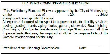
N. Signature Block and statement for Preliminary Plan and Plat approval by the Planning Commission. The statement shall read:
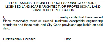
O. Signature Block for Engineer and/or Surveyor. A Statement of Accuracy shall be placed on the Preliminary Plat and Plan and the Final Plan and Plat cover sheet, signed and dated by the Engineer and/or Surveyor. The Statement shall read:
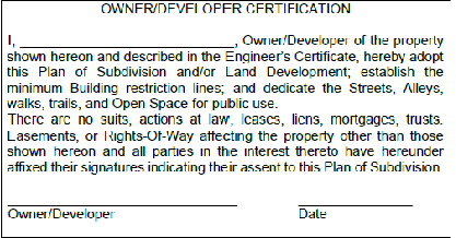
P. Signature of Owner/Developer. A Statement of Acceptance shall be placed on the Preliminary Plat and Plan and the Final Plan and Plat cover sheet, signed and dated by the Owner/Developer. The Statement shall read:
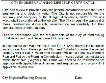
Q. Signature of City Engineering Planning Department. A Statement for construction approval shall be placed on the Final Plan cover sheet, signed and dated by the City Engineer/Planning Director or designee. The Statement shall read:
R. Note on the Plan or Plan, “This property is not (is) in an area designated as a special Flood area, as shown on Community Map/Panel Number _____/Effective date _____.”
S. Note on the Plat or Plan, the West Virginia DOH entrance permit number and provide a copy of the entrance permit.
T. Note on the Plat or Plan, the West Virginia Department of Environmental Protection (DEP) permit numbers for all DEP approvals required for the project.
U. Source of Topography and date.
V. Note regarding any known Sinkholes, steep Slopes, rock outcroppings, Wetlands and streams.
W. Parking calculations – required and provided.
X. As-Built certificate.
Y. Construction including grading certificate.
Z. SESC and SWM certificate.
AA. Table 1305-2, listing Waivers approved by the Martinsburg Planning Commission and Variances and Special Exceptions approved by the Martinsburg Board of Zoning Appeals shall be placed on the Preliminary Plan, Site Plan or Final Plat cover sheet, as applicable. If no Waivers or variances are granted, then a statement of “None granted,” shall be placed in the table:
Table 1305-2, Complete List of Waivers, Variances, or Special Exceptions
Martinsburg - Complete List of Waivers, Variances, or Special Exceptions | |||
Ordinance | Section of Ordinance | Description of Waiver, Variance, or Special Exception | Date Granted |
(2) Existing Conditions (Scale 1” = 100’ or less).
A. Title Block, North arrow and scale (both numerical and graphic).
B. The boundary lines of the parcel(s) subject to the Subdivision and/or Land Development, accurate in scale and bearing, together with a legal description of such parcel(s).
C. The Berkeley County district tax map and parcel numbers, and deed book and page numbers of the recorded deed into the current owner(s), of each parcel subject to the Subdivision and/or Land Development.
D. The location and names of adjoining Subdivisions, and the locations and tax map and parcel numbers of adjoining parcels of land, deed book reference, Zoning District and use, together with the names of the owners of record of such parcels. This shall be shown on all applicable sheets.
E. The layout of existing Lots and dimensions and area in square feet.
F. The location (by lines and bearings), widths (or other relevant dimensions), and names of all existing or platted Streets, Alleys, public ways, pavement and Easements/Rights-Of-Way, within and adjacent to the parcel subject to the Subdivision and/or Land Development, and other important features such as existing permanent Buildings, large trees, railroad lines, Watercourses, etc. The general purpose of Easements and Rights-Of-Way shall be indicated.
G. Existing contours, normally with intervals of two (2) feet, referenced to a permanent benchmark. For areas with Slopes greater than twenty-five percent (25%), five (5) feet contour interval may be used.
H. Show and note the existing front, side, and rear yard Setbacks as set forth in the City of Martinsburg Zoning Ordinance and incorporated herein by reference under Section 1301.08, or at a greater depth established by restrictions, covenants and/or conditions in deeds, declarations, or other documents of record (or to be recorded).
I. Delineation and location of any significant environmental features, including without limitation:
1. Streams.
2. Wetlands.
3. Floodplains.
4. Soils and soils information.
5. Highly erodible soils.
6. Riparian areas and tree lines.
7. Sinkholes or depressions.
J. Location of municipal boundary lines, if applicable.
K. Location of Zoning District boundary lines if they border upon or cross any part of a parcel subject to the proposed Subdivision and/or Land Development.
L. All survey Monuments, Lot corners, Block markers, and benchmarks, together with their description, including location and description of all USGS survey control Monuments, or equivalent.
M. Built Structures.
N. Power transmission towers or power lines; cable; and telephone lines.
O. Historic area and/or features.
P. Existing restrictive Easements, other Easements, and Rights-Of-Way and use.
Q. Parks and/or public open space.
R. Forested areas and tree groves.
S. Outstanding topographic features, including prominent rock outcroppings.
T. Location, width, and names of all existing Streets or Alleys within one hundred (100) feet of the project site, including State Route numbers, if applicable.
U. All existing Easements and Rights-Of-Way shall be accurately identified, located, dimensioned and drawn to scale. Provide reference to deed book and page and/or Plat book and page, whichever applies.
(3) Preliminary Plat. If the proposed Subdivision or Land Development contemplates Structures or other Improvements upon the land, supplemental construction/Development Plans and drawings that include and illustrate the following information shall constitute, and be submitted as, part of the Preliminary Subdivision Land Development Application, to the extent such information is applicable to the proposed Subdivision Land Development:
A. Title Block, North Arrow and Scale.
B. Site Map (scale of 1” = 50’ or less).
C. Proposed Lots with dimensions, area, front, side and rear yard Setbacks. Lot numbers shall be in consecutive order.
D. Locations of existing and proposed water, sanitary sewer, gas, electric and all other underground utilities, including locations, size and composition of all main lines, valves, utility holes, fire hydrants and other equipment and fixtures. A note on the Plan shall state: “All proposed utilities shall be located underground.”
E. Location of all Street signs and traffic control signs required pursuant to Section 1307.02
(m) of this Ordinance.
F. Proposed Streets that are clearly aligned with existing Streets shall bear the name of the existing Street. In no other case shall the names of the proposed Streets be duplicated or be phonetically similar to an existing street name, irrespective of the suffix: Street, avenue, court, place, boulevard, land, drive, or other. All proposed Street names shall be submitted to the Berkeley County Central Dispatch for approval.
G. Location and widths of sidewalks and pedestrian/bike trails, if applicable.
H. The location, size and materials of all existing and proposed sanitary sewers and sewerage facilities, equipment, fixtures and Structures within and immediately adjacent to the parcel subject to the Subdivision and/or Land Development, including: utility holes (including the top of casting elevations and invert elevations and materials of construction and diameters of all pipes entering and exiting); sewer main pipe diameters, type, length and Slope between all utility holes; service lateral pipe size and type; clean-outs; valve pits, and force mains; all together with grades and other specifications designated as “existing”
I. The location, size and materials of all existing and proposed storm sewers, catch basins, culverts and other Drainage and Stormwater Management Facilities, equipment, fixtures and Structures within and immediately adjacent to the parcel subject to the Subdivision and/or Land Development, including without limitation pipes, channels, and inlets/outlets; all together with grades and other specifications designated as “existing” or “proposed.”
J. The location, size and materials of all existing and proposed combined sewer facilities, equipment, fixtures and Structures within and immediately adjacent to the parcel subject to the Subdivision and/or Land Development, including utility holes and drop inlets (including the top of casting elevations and invert elevations and materials of construction and diameters of all pipes entering and exiting); combined sewer main pipe diameters, type, length and Slope between all utility holes and drop inlets; service lateral pipe size and type; clean-outs; and Stormwater Detention system piping and appurtenances; all together with grades and other specifications designated as “existing” or “proposed.”
K. The location of all vehicular ingress and egress to the parcel(s) subject to the Subdivision and/or Land Development, and all parking areas proposed thereon.
L. The locations and dimensions of all Buildings and Structures intended to be constructed on the parcel(s) subject to the Subdivision and/or Land Development.
M. Adjacent Property Owners, Deed book, Page and Zoning
N. Proposed and existing Easements.
O. Property corners.
P. Existing and proposed Streets.
Q. Parking Lots with space calculations
R. FEMA Floodplain boundaries labeled and delineated.
(4) Grading Plan.
A. Two-foot topography – existing and proposed contours.
B. All Drainage features.
C. Rip-rap aprons to scale and labeled.
D. Proposed Streets, pads – indicate curb, gutter, edge of pavement.
E. Spot Elevations for all pertinent features.
F. Location of benchmarks.
G. Lot grading to include first floor elevations, garage floor elevations, basement floor elevations, and Driveway Slopes.
H. Permanent Erosion control features.
I. Accessible parking spaces to meet ADA requirements.
J. FEMA Floodplain delineated and labeled.
(5) Utility Plan.
A. All existing and proposed water lines, fire hydrants, valves, components, and force mains. Connection locations, pressure and flows at connection points.
1. All existing and proposed sewer lines, force mains, manholes, etc. Inverts at connection points and capacities of system receiving flow along with flow direction.
2. Pumping station and any other Improvements.
B. Storm sewer size, type, material, Slopes, inverts, inlet and manhole tops, etc. labeled for all features – pipes, inlets, end sections, etc.
1. All proposed and existing utility Easements.
(6) Road Plan and Profiles (may be shown on the same sheet).
A. Road Plan (scale of 1” = 50’ or less).
1. Stations and profiles of all existing, platted and proposed Streets and Roads at minimum fifty-foot intervals.
2. Crossings.
3. Existing and proposed grade and approach grades labeled.
4. Turning flare radii labeled at Intersections.
5. Horizontal curve radii and geometric data.
6. Drainage features.
7. Guardrail locations.
B. Road Design Profile (scale of 1” = 50’ horizontal and 1” = 5’ vertical).
1. Proposed grade and existing grade of all proposed Streets and Roads.
3. Waterlines.
(7) Public Street Cross Sections (Scale of 1” = 5’ on 50 foot intervals).
A. Original grade and Cut and Fill limits.
B. Typical cross section showing Road/shoulder width, thickness, type of pavement and base.
C. Location, width and thickness of sidewalks.
D. Location, composition and size of utility main lines.
E. For embankment Slopes exceeding a 3:1 horizontal to vertical Slope, provide Street cross-sections at twenty-five (25)-foot intervals.
(8) Sewer Plan Profile.
A. Existing and proposed grades.
B. Stationing every fifty (50) feet minimum.
C. Stationing of pertinent features.
D. Labeling of all inverts, top of manholes, crossings, etc.
E. Size, types, material, length, Slopes, tops, labeled for all appurtenances.
(9) Storm Sewer Profiles.
A. Existing and proposed grades.
B. Size, types, material, length, Slopes, tops, labeled for all appurtenances.
C. Inverts, top of inlets, etc. shown and labeled.
D. Schedule of inlets and manholes to include Structure number, size, types, etc.
E. Driveway culvert chart.
F. Q25 and V25 labeled on all charts.
G. Design Tables.
H. Rip Rap aprons shown and labeled with sizing data on all outlets.
I. Twenty-five (25)-year Hydraulic Grade Line (HGL) shown on all storm sewer runs.
(10) Soil and Sediment Control Plan.
A. Existing and proposed grades.
B. Soil areas delineated and labeled.
C. Drainage areas delineated and provided for Sediment Control features.
D. Silt fence, super silt fence, diversion dikes and ditches, inlet/outlet protection, rip rap aprons, stone check dams, etc. shown clearly.
E. Silt traps and basins shown with details, sizing calculations, dewatering devices and profile view.
F. Stabilization measures of all Slopes, channels and concentrated flow areas clearly shown.
G. Stockpile areas with silt fence downgrade.
H. Total disturbed areas delineated and labeled.
(11) Soil and Sediment Control Plan Details.
A. Details of all soil and Sediment Controls.
B. Permanent and temporary seeding notes.
C. Maintenance schedule and instructions.
(12) Storm Water Management Plan, Profiles and Notes.
A. Profiles through ponds and embankments showing proposed and finished grades.
B. Basic pond or water quality Structure dimensions.
C. Show top of Berm with top of settled Berm, spot elevations, core trench, impervious core, anti-seep collars, low flow orifice protections, and emergency spillway.
D. Structural details for all storm water management features.
E. Landscaping Plans, storm water management plantings and aquatic vegetation schedule.
F. Maintenance schedule and instructions.
G. Outlet dissipation devices shown to scale with details.
H. Any required Easements.
(13) Notes and Details.
A. General project notes.
B. Construction notes.
C. Grading and Drainage notes.
D. Road notes and typical Road cross sections.
E. Water and sewer notes and details.
F. Sequence of construction.
G. Sediment Control notes.
H. Symbols legend.
I. All Street and traffic control signage.
J. Sidewalk and curb and gutter details.
K. Drainage details.
L. Parking details including ADA accessibility ramps.
(14) Landscaping Plan.
A. Delineate buffers and planting screen Easements.
B. Type of plantings and how many of each.
(15) Additional Items. The following items shall be submitted as part of a Preliminary Subdivision and/or Land Development Application, to the extent such items are applicable to the proposed Subdivision and/or Land Development.
A. Stormwater Management Report. A written report to meet the requirements of the Stormwater Management Ordinance.
B. Covenants, Conditions and Restrictions. Two (2) copies of any private restrictions, covenants and/or conditions to which any portion of the parcel(s) subject to the Subdivision and/or Land Development is subject or will be made subject, whether by deed, declaration or other instrument.
C. Agency Reviews. Review comments from relevant local, state, and federal agencies with jurisdiction with respect to the land and activities thereon, and approvals thereby or permits issued thereby, to the extent the same are required. Relevant agencies may include, but are not limited to:
1. City of Martinsburg.
2. Berkeley County Central Dispatch.
3. Berkeley County Health Department.
4. West Virginia Department of Environmental Protection, hereinafter referred to as West Virginia DEP.
5. West Virginia Department of Transportation, Division of Highways, hereinafter referred to as West Virginia DOH.
6. U.S. Army Corps of Engineers.
7. Federal Aviation Administration.
D. Traffic Impact Study. A West Virginia DOH approved Traffic Impact Study as required under Section 1307.07
(b), Traffic Management Standards of this Ordinance or by the West Virginia DOH.
E. Lighting Plan. A lighting Plan containing the information and items required under Section 1307.13
.
(Ord. 2022-13. Passed 11-10-22.)