Figure 1: Typical Residential Lot Grading
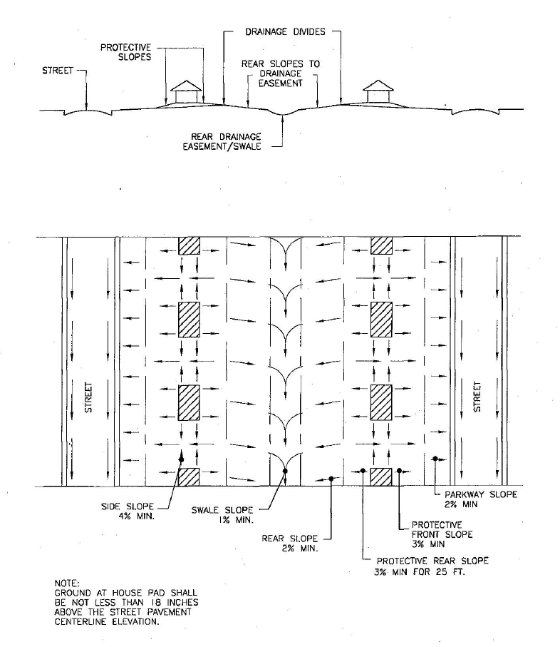
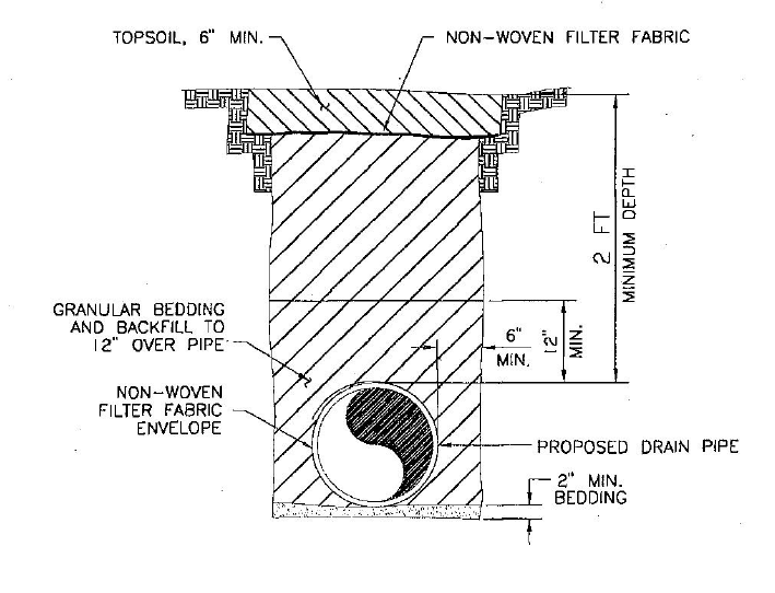
Figure 2: Underdrain Trench Detail
Typical Lot Drainage Detail
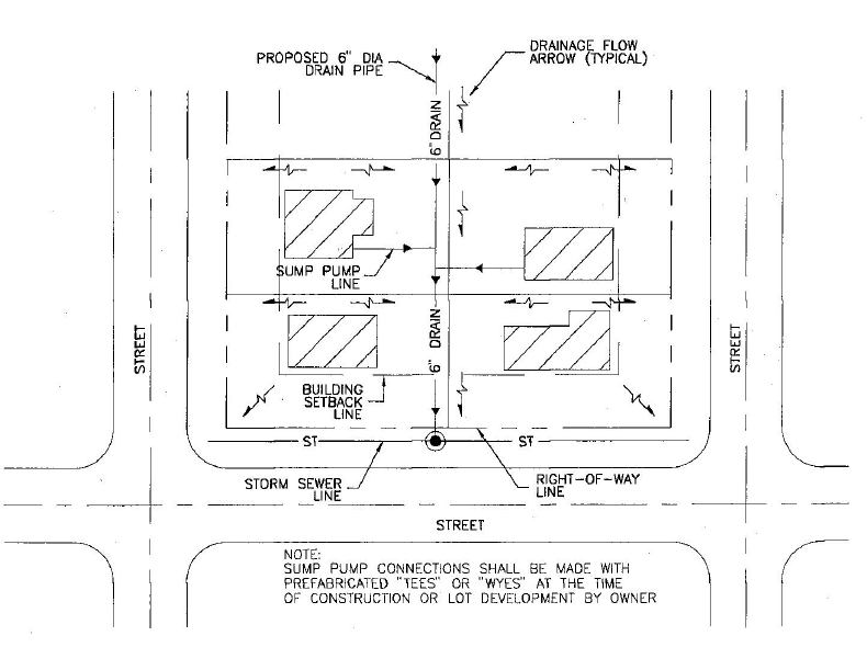
Figure 3: Portland Cement Concrete Pavement Joint Layout
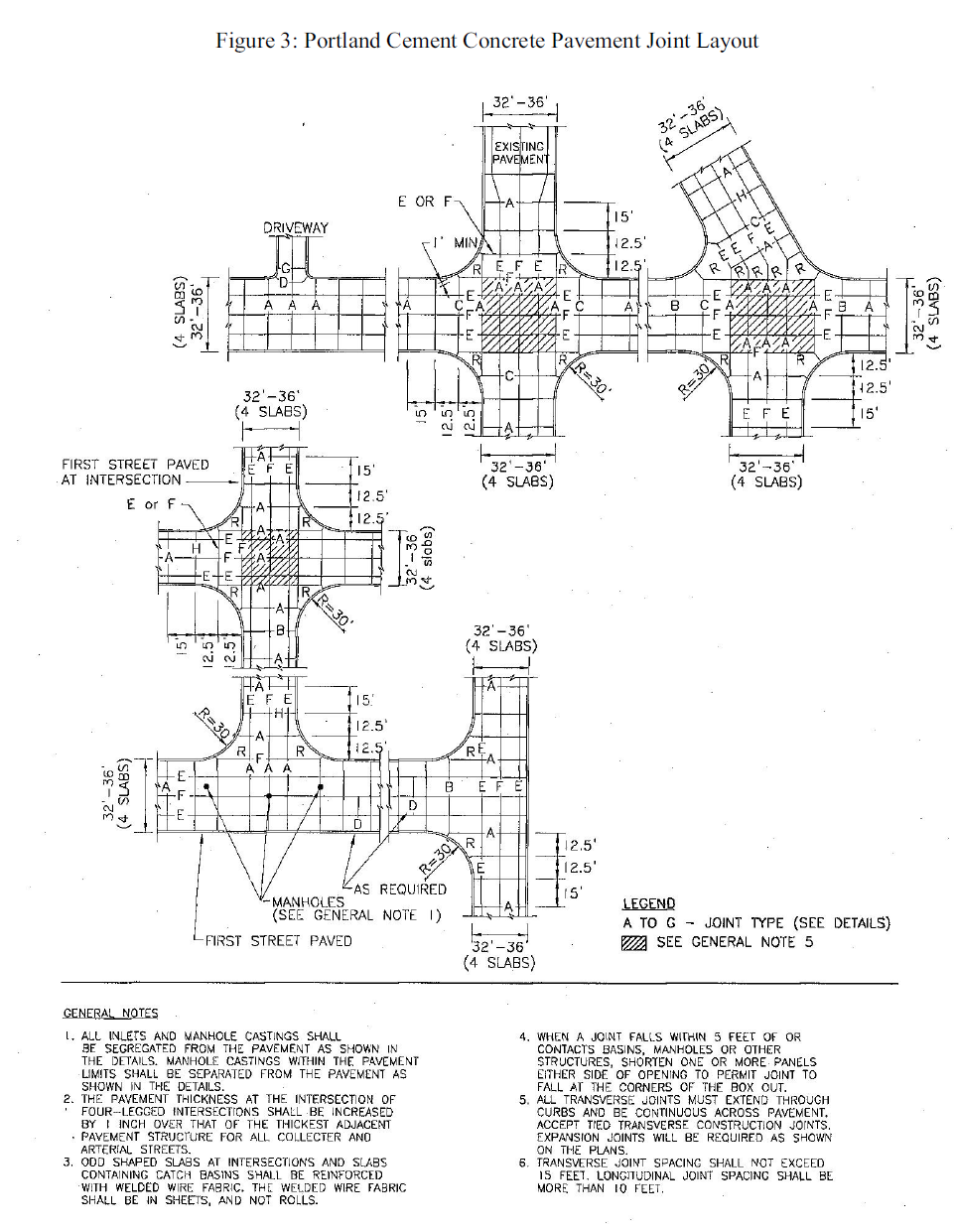
Figure 4: PCC Pavement Joint Details
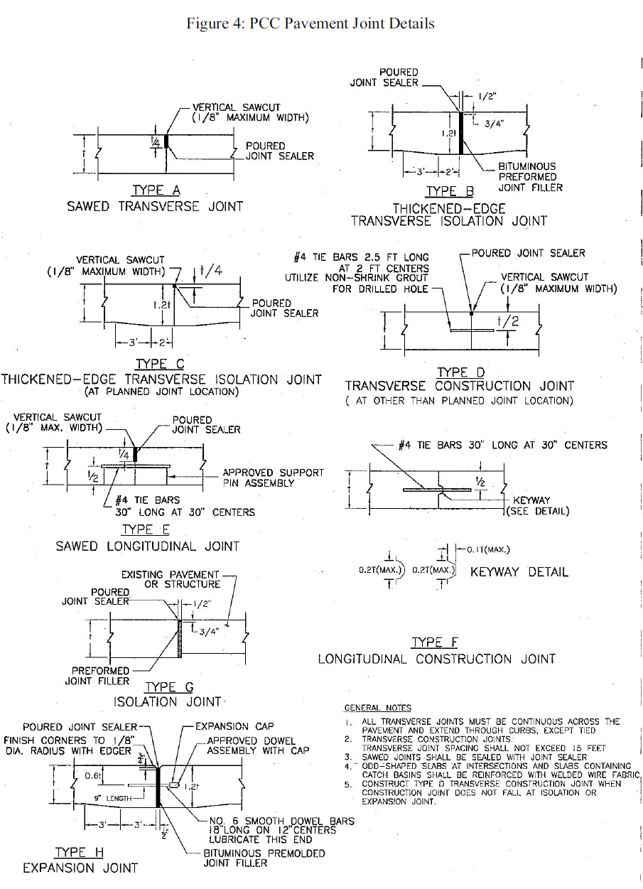
Figure 5: PCC Pavement Details at Manholes
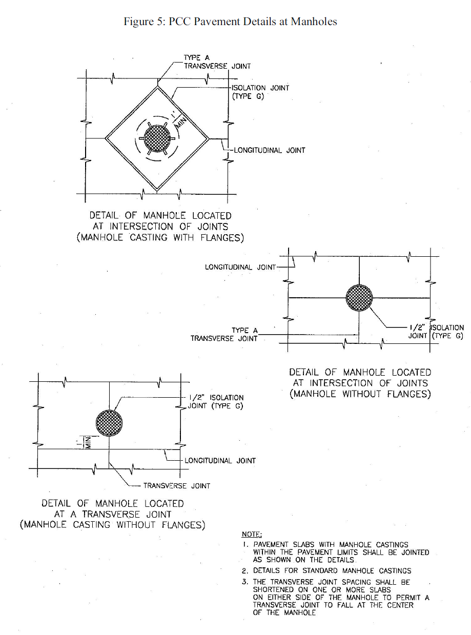
Figure 6: PCC Pavement Details at Inlets
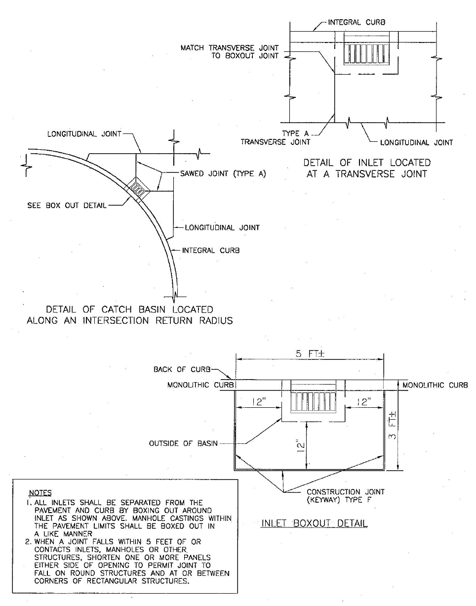
Figure 7: Cul-de-sac Pavement Joint Layout
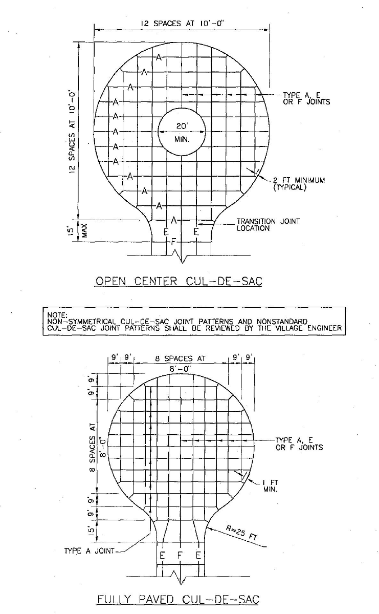
Figure 8: Longitudinal Joint Spacing for Streets
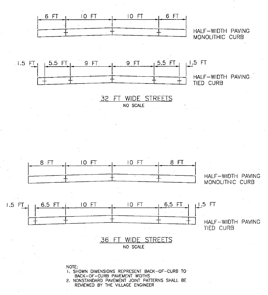
Figure 9: Curb Details
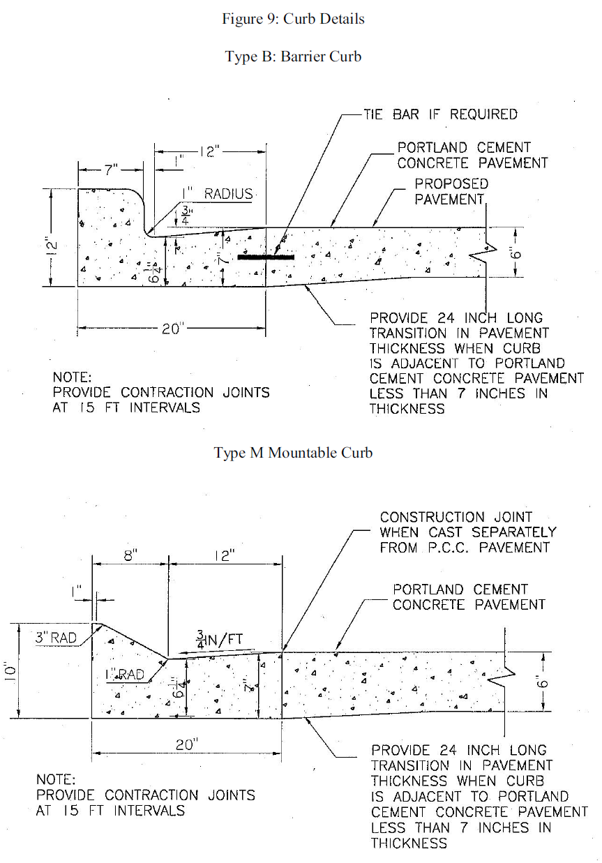
Figure 10: Street Sign Details

Figure 11: Typical Sidewalk Ramp Detail
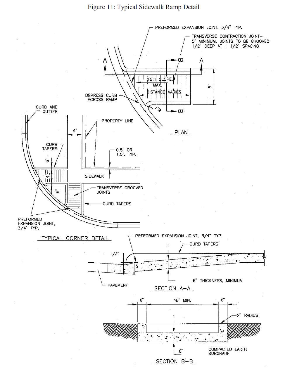
Figure 12: Thrust Block Installations
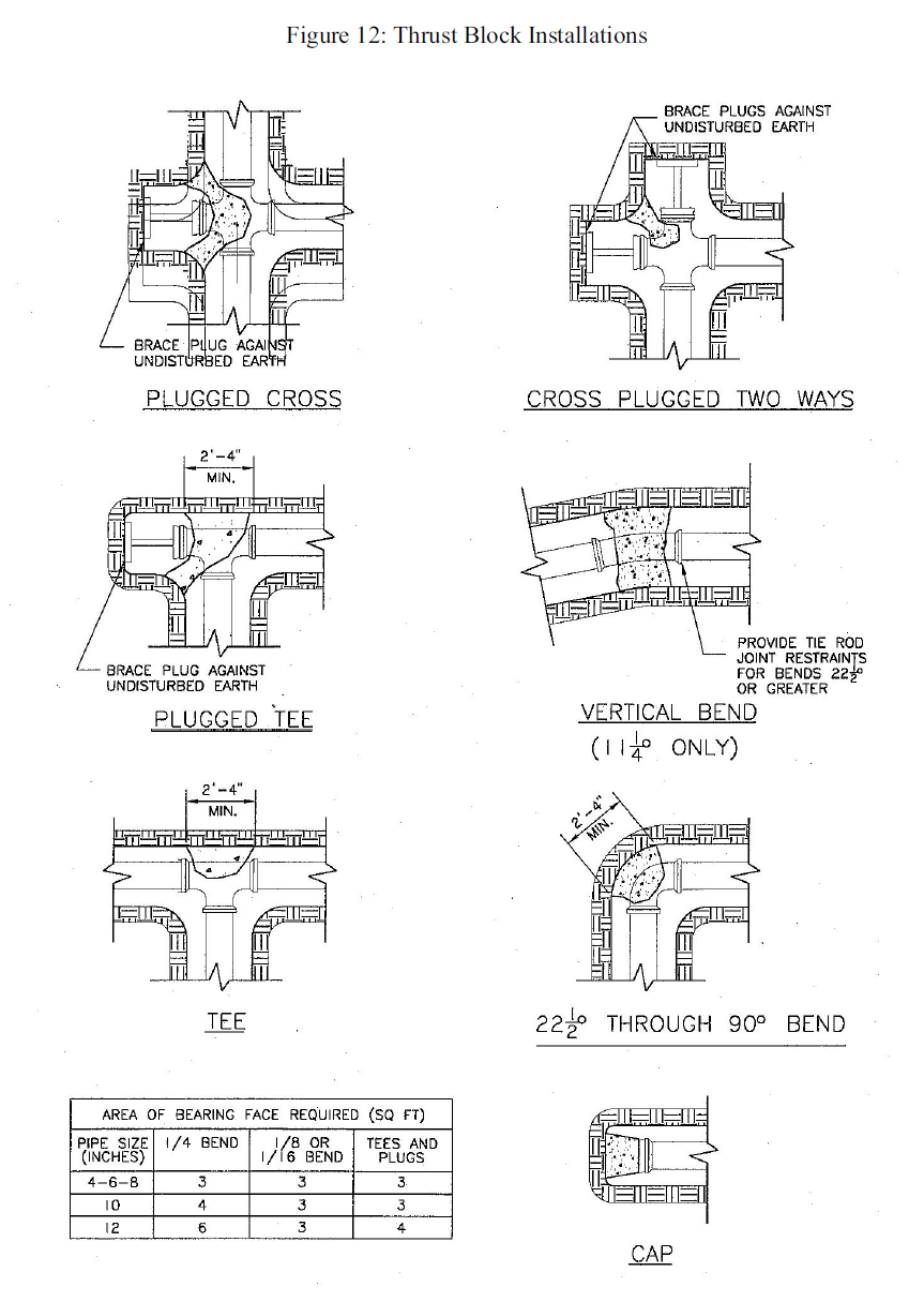
Figure 13: Anchorage of Fittings in a Vertical Plane
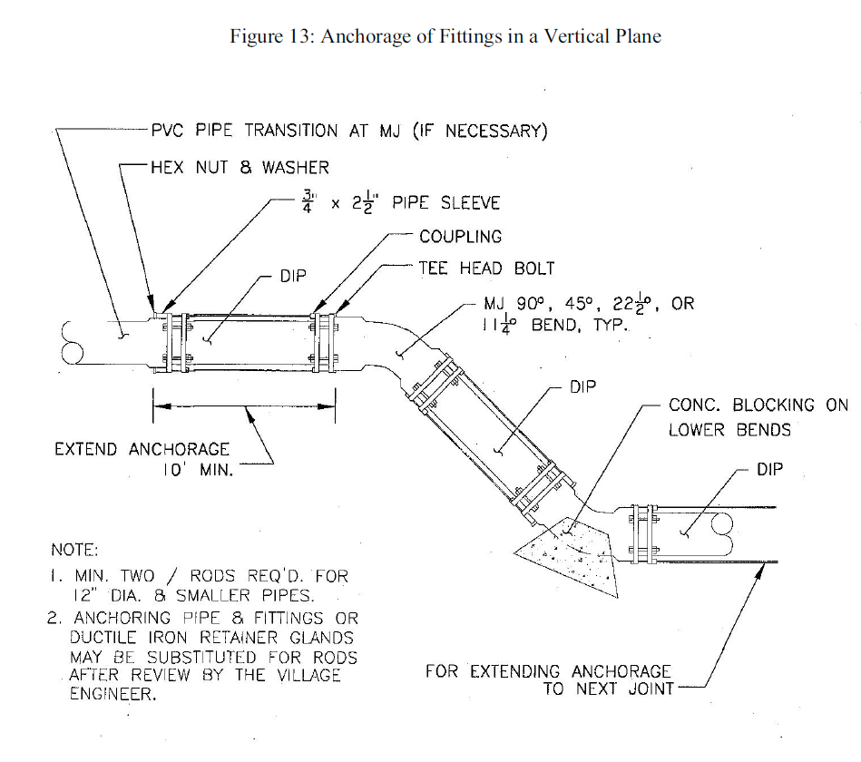
Figure 14: Curb Stop and Box and Service Tubing
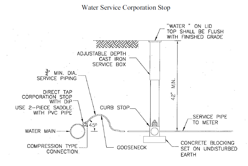
Water Service Corporation Stop
Valve Box Detail
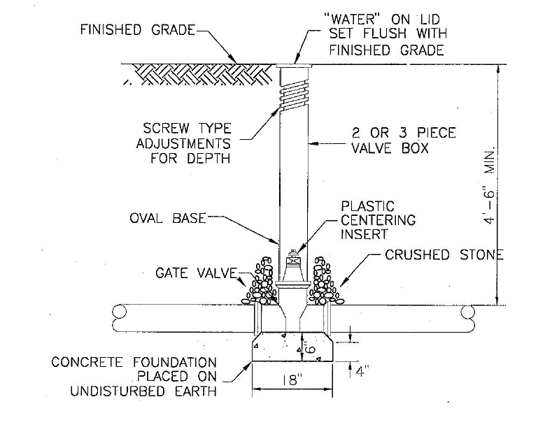
Figure 15: Typical Water Service Shutoff Valve Location
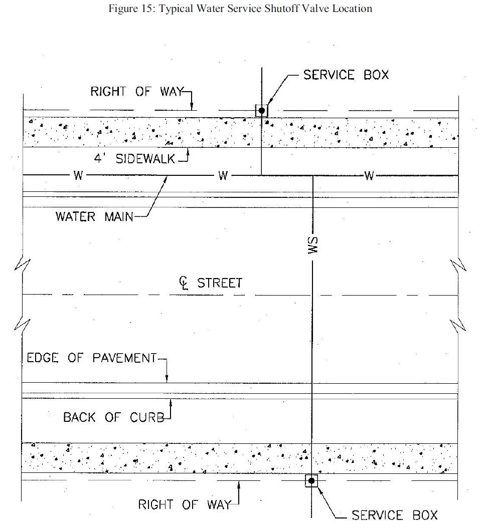
Figure 16: Fire Hydrant Setting Detail
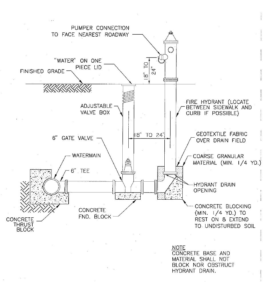
Figure 17: Service Riser Detail
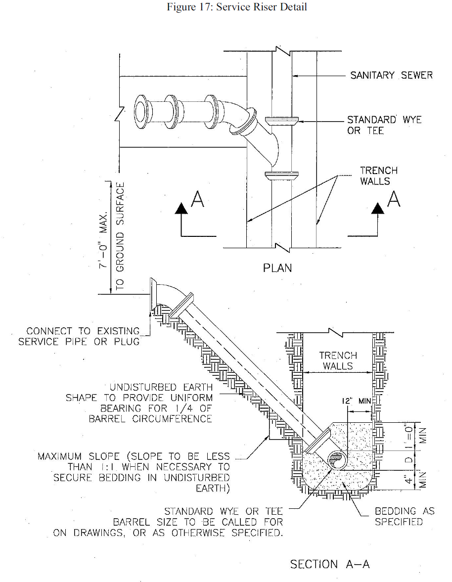
Figure 18: Cleanout Detail
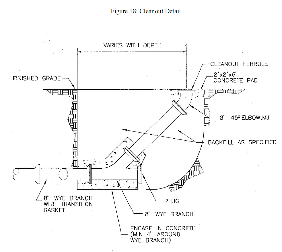
Figure 19: Trench under Yards and Unimproved Areas, Method I
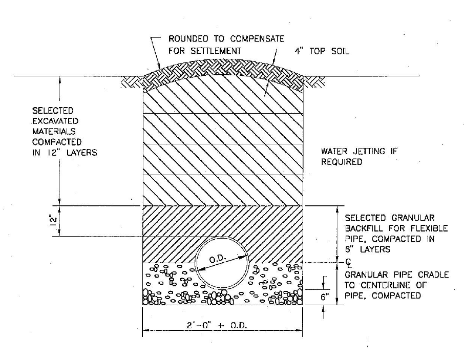
Figure 20: Trench in Parking Areas, Driveways, and Alleys Not Having Permanent Surfaces Nor Having Oil and Chip Surfaces, Method II
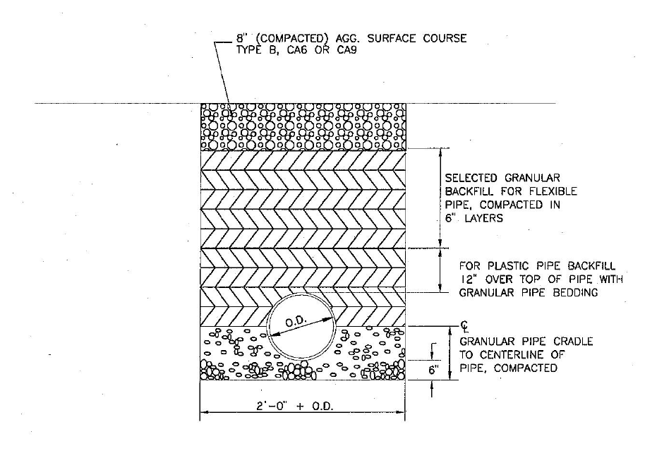
Figure 21: Trench under Existing Utilities or Structures (Extending Two Feet on Either Side of the Utility), Method III
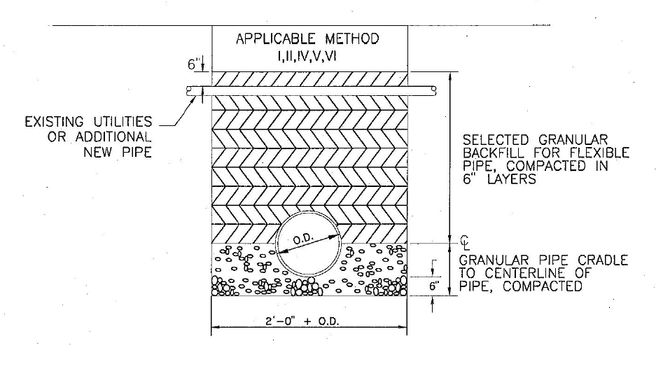
Figure 22: Trench under Permanent Concrete Surface, Method IV
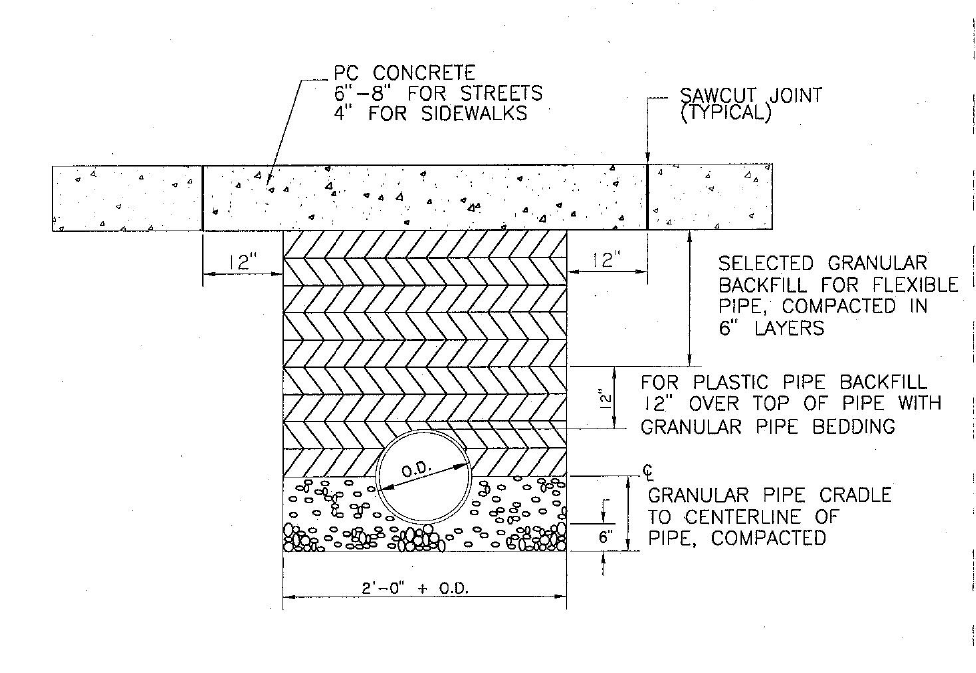
Figure 23: Trench under Flexible Pavement or Oil Chip Streets, Method V
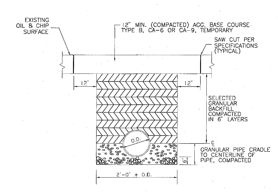
Figure 24: Trench under Cultivated Fields, Method VI
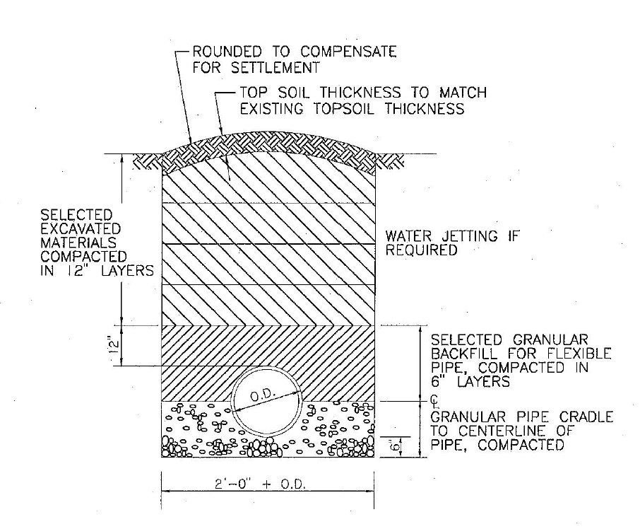
Figure 25: Trench in Lagoon Dike or Berm, Method VII
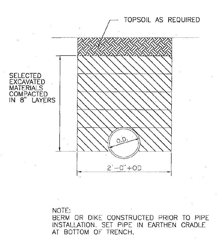
Figure 26: Repair of Existing Drain Tiles in Piping Trench
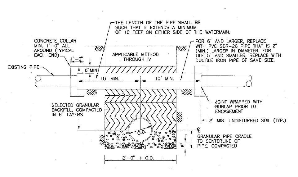
Figure 27: Typical Sanitary Manhole
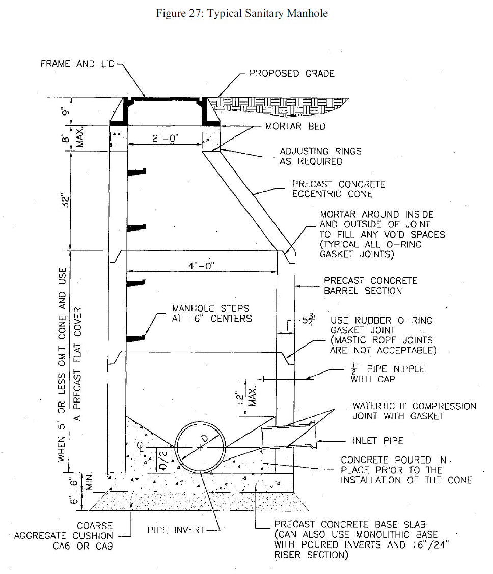
Figure 28: Typical Storm Manhole with Cone
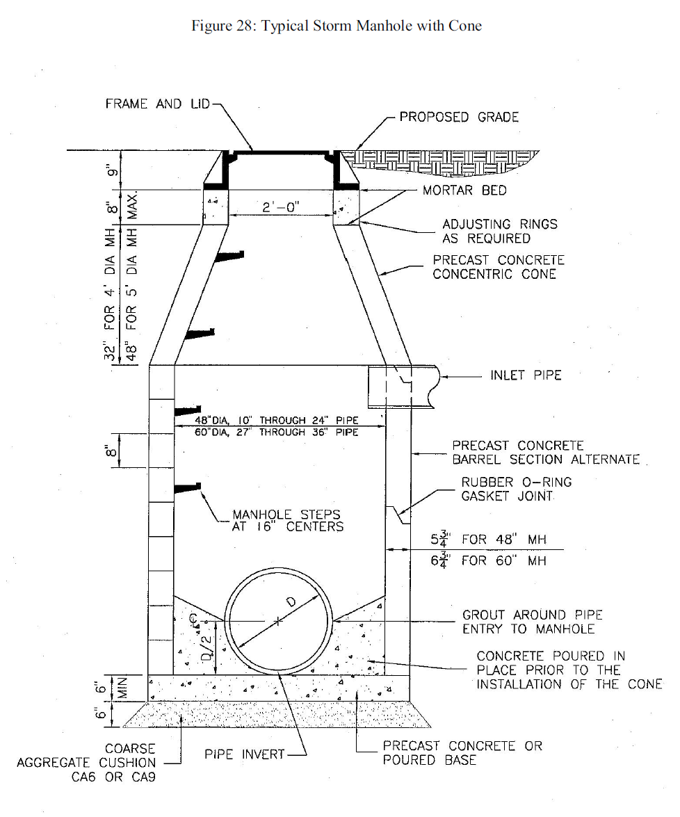
Figure 29: Typical Storm Manhole with Flat Top
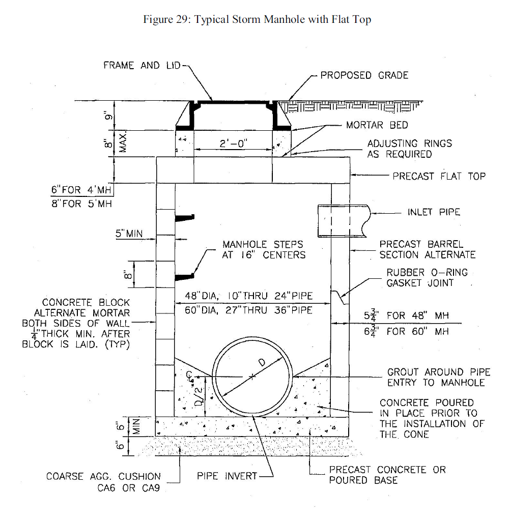
Figure 30: Precast Concrete Flat Top Section
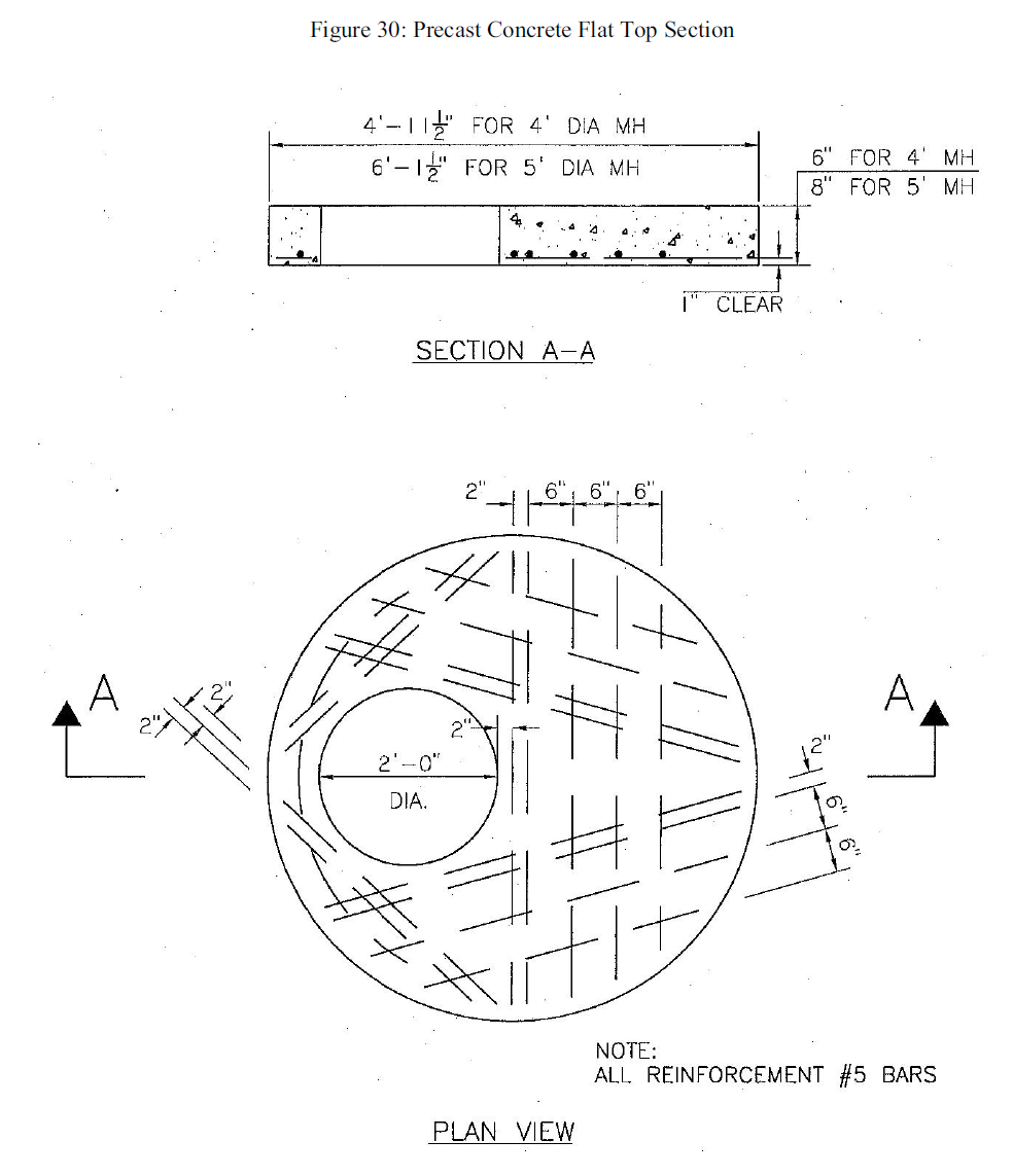
Figure 31: Drop Manhole Connection Detail
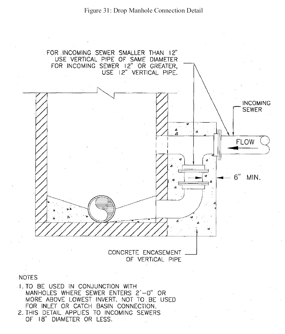
Figure 32: Detail of Catch Basin
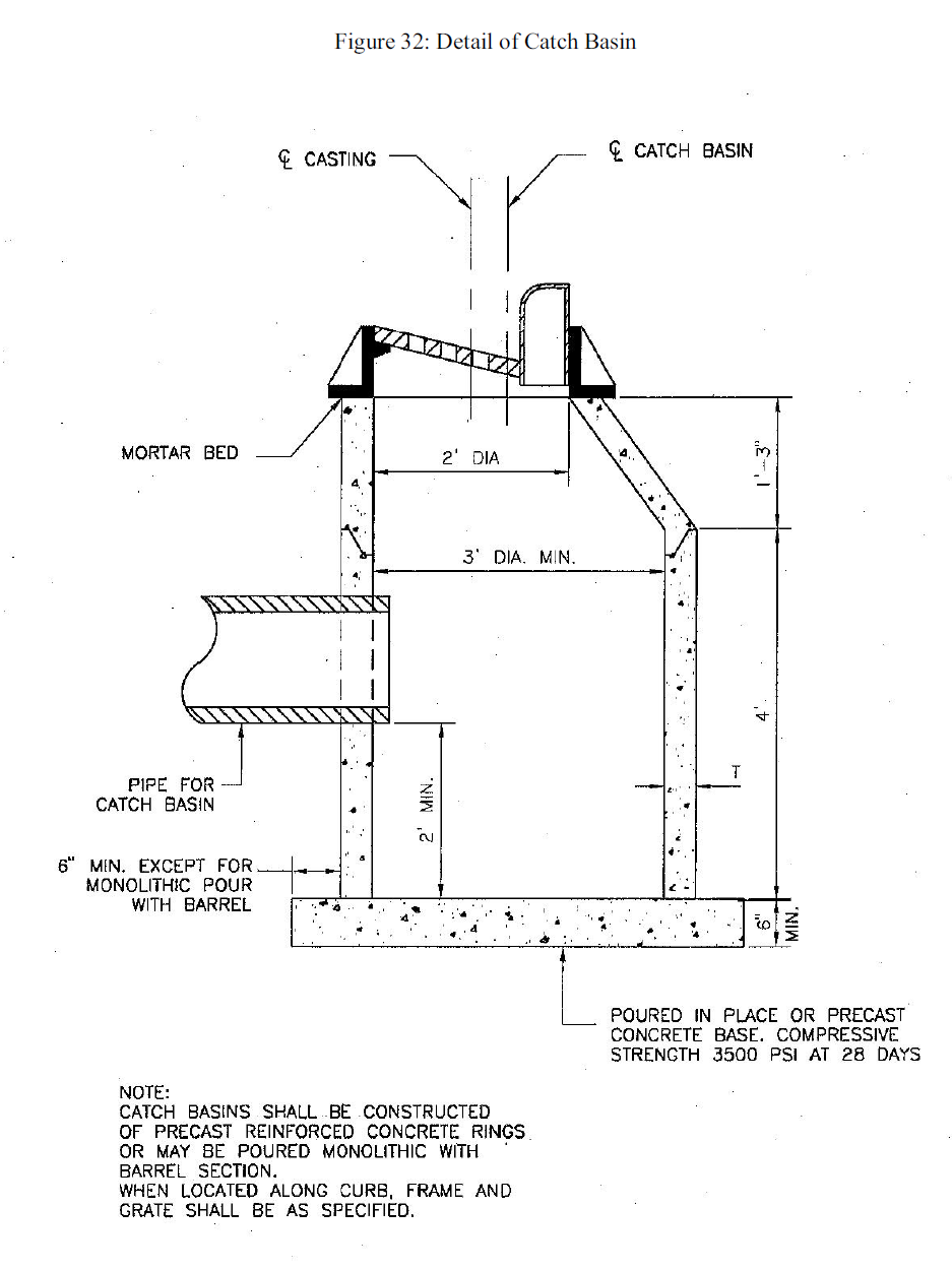
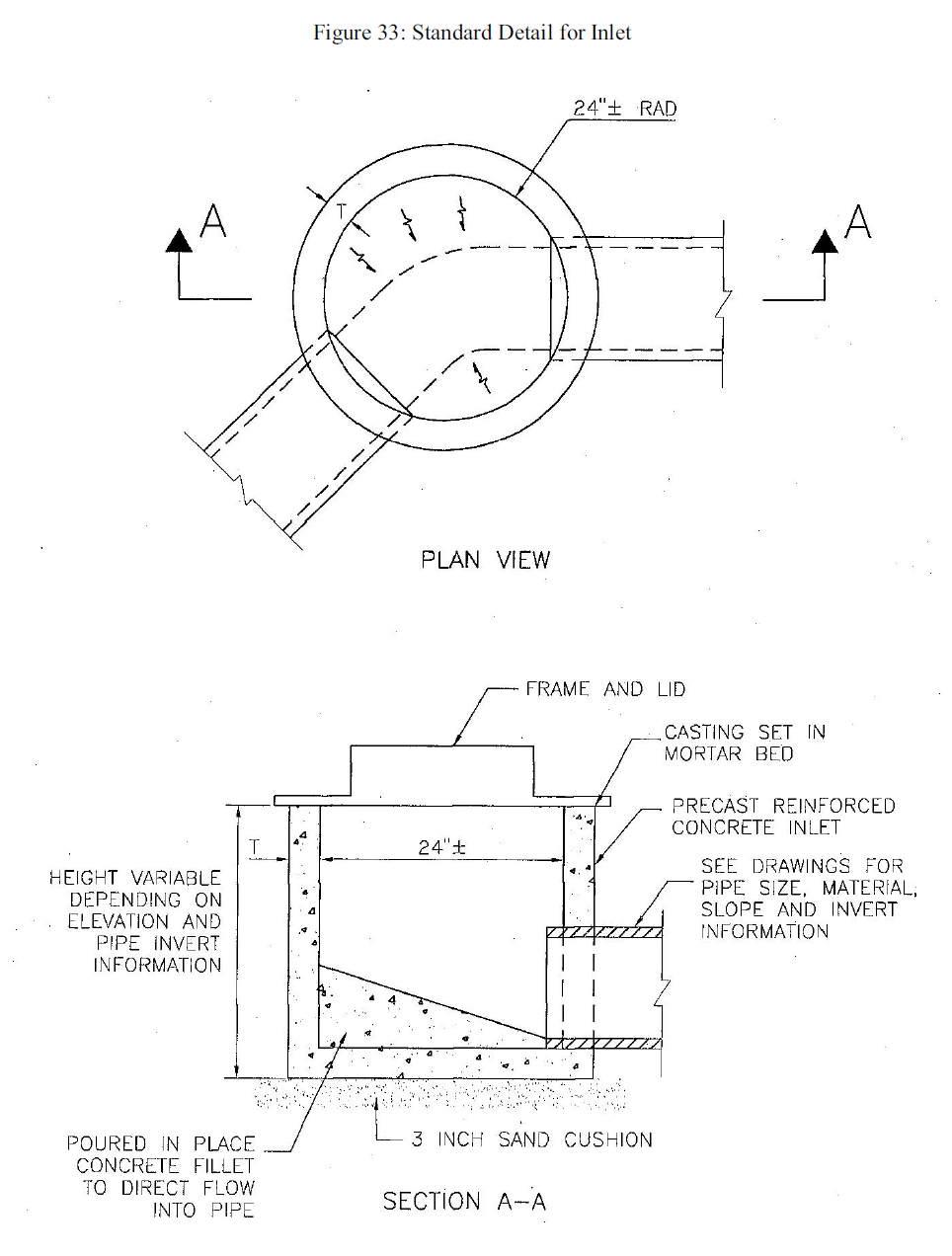
Figure 33: Standard Detail for Inlet