Village of Westfield Center, Ohio
Construction & Material Specifications
And Standard Construction Drawings
Introduction
These Construction and Materials Specifications and Standard Construction Drawings apply to all improvements within existing and proposed Village of Westfield Center right-of-way. The specifications contained herein, in general, reference the State of Ohio Department of Transportation (ODOT) Construction and Materials Specifications, current edition. All applicable portions of the ODOT specifications so referenced shall apply to work performed hereunder as if incorporated herein. Specific references to materials herein shall serve to limit the acceptable ODOT materials to only those so referenced.
Village of Westfield Center, Ohio
Construction and Material Specifications
Pavement
Rigid Pavement
Sub-grade Compaction - ODOT 203
Aggregate Base - ODOT 304
Limestone aggregate only
Plain Concrete Pavement - ODOT 452
Limestone coarse aggregate only
Integral Concrete Curb (Type 2-A) - ODOT 609
Limestone coarse aggregate only
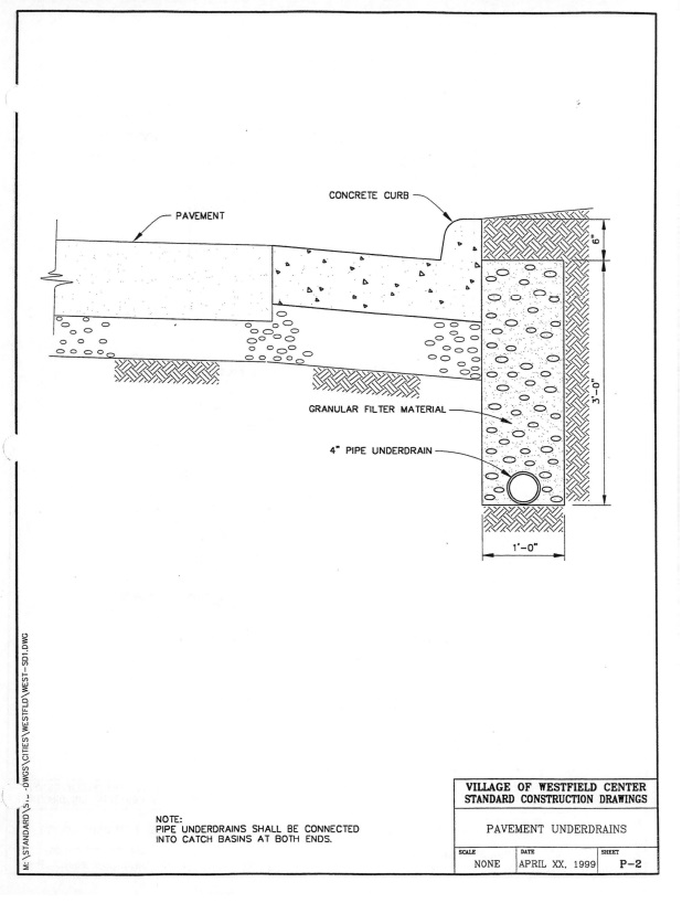
Pipe Under-drains - ODOT 605
Corrugated Polyethylene Drainage Tubing (Perforated) - ODOT 707.31
Polyvinyl Chloride Plastic Pipe - ODOT 707.41
Flexible Pavement
Sub-grade Compaction - ODOT 203
Aggregate Base - ODOT 304
Limestone aggregate only
Bituminous Aggregate Base - ODOT 301
Asphalt Concrete Intermediate Course - ODOT 403
Limestone coarse aggregate only
Asphalt Concrete Surface Course - ODOT 404
Limestone coarse aggregate only
Combination Concrete Curb and Gutter (Type 2) - ODOT 609
Limestone coarse aggregate only
Pipe Under-drains - ODOT 605
Corrugated Polyethylene Drainage Tubing (Perforated) - ODOT 707.31
Polyvinyl Chloride Plastic Pipe - ODOT 707.41
Roadside
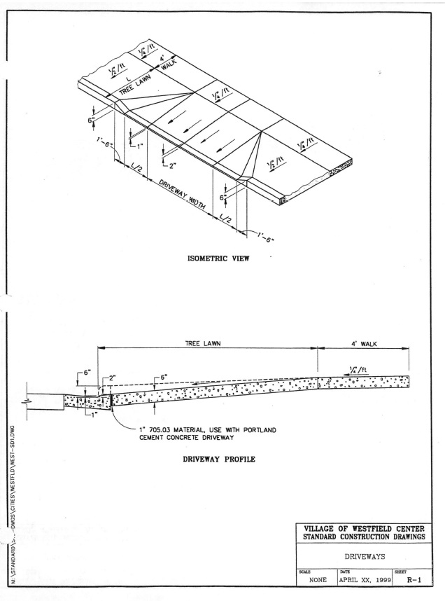
Driveways - ODOT 452
Limestone coarse aggregate only
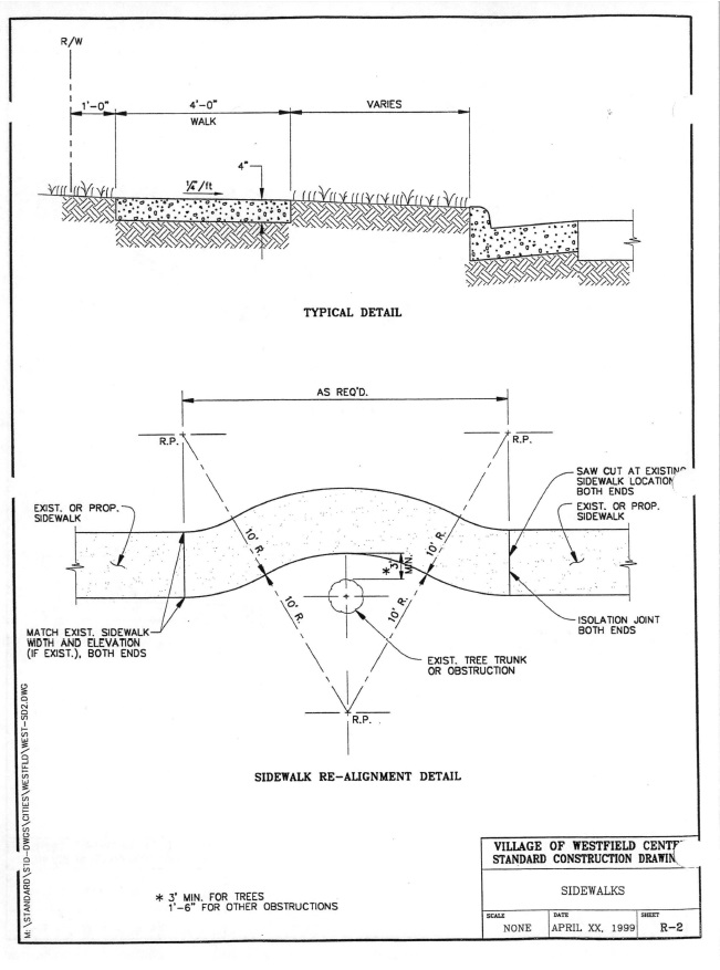
Concrete Sidewalks - ODOT 608
Limestone coarse aggregate only
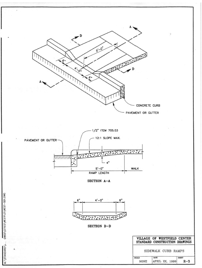
Concrete Curb Ramps - ODOT 608
Limestone coarse aggregate only
Seeding - ODOT 659
Storm Sewers
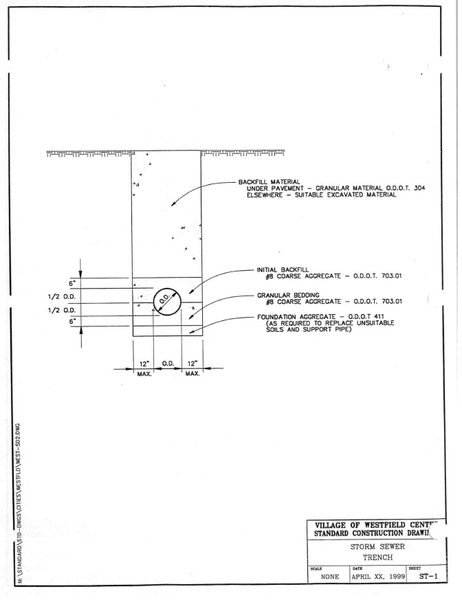
Storm Pipe - ODOT 603
Reinforced Concrete Pipe - ODOT 706.02
Polyvinyl Chloride Solid Wall Pipe - ODOT 707.45
Corrugated Polyethylene Smooth Lined Pipe - ODOT 707.33
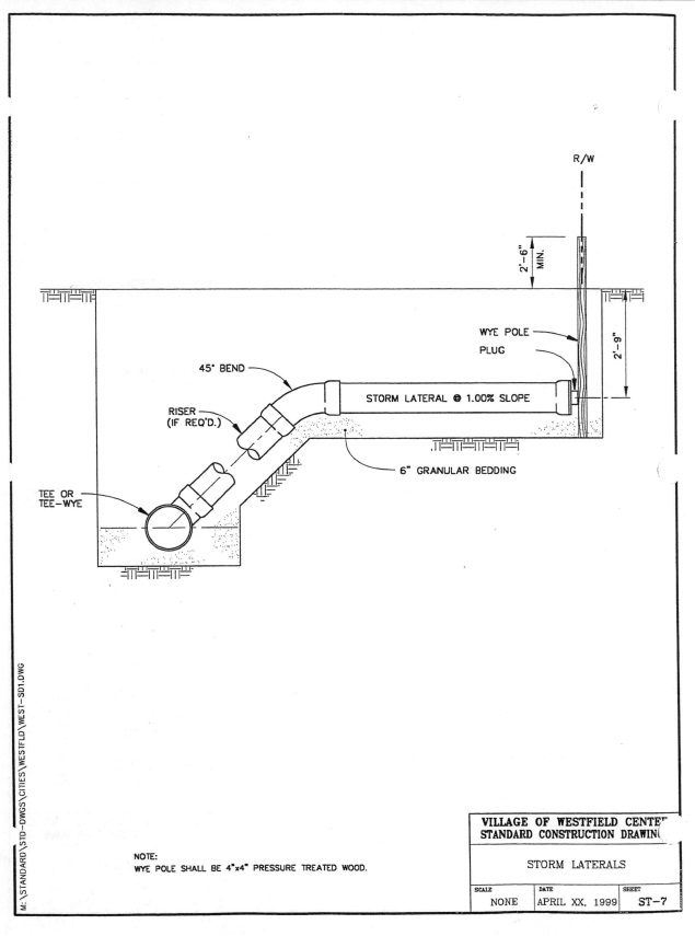
Lateral Pipe - ODOT 603
Polyvinyl Chloride Solid Wall Pipe - ODOT 707.45
Corrugated Polyethylene Smooth Lined Pipe - ODOT 707.33
Catch Basins - ODOT 604
Basins - Precast Reinforced Concrete - ODOT 706.13
Castings - Gray or Ductile Iron - ODOT 711.12 or ODOT 711.13
Type 3 - East Jordan Iron Works 7031 with grate or approved equal
Type 3A - East Jordan Iron Works 7030 with grate or approved equal
Type 2-2B - East Jordan Iron Works 5370 frame with grate or approved equal
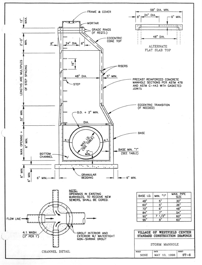
Manholes - ODOT 604
Manhole - Precast Reinforced Concrete - ODOT 706.13
Castings - Gray or Ductile Iron - ODOT 711.12 or ODOT 711.13
Heavy Duty (Pavement Areas) - East Jordan Iron Works 1058 or approved equal with solid cover, machined bearing surfaces and “STORM SEWER” cast in the cover
Light Duty (Non-Pavement Areas) - East Jordan Iron Works 1022 or approved equal with solid cover, machined bearing surfaces and “STORM SEWER” cast in the cover
Steps - Reinforced Propylene Plastic Manhole Steps - ODOT 711.31 M.A. Industries, Inc. Model PS1-PF or approved equal
Sanitary Sewers
Sanitary Gravity Pipe - ODOT 603
Polyvinyl Chloride Sanitary Pipe - ODOT 707.44 (SDR 35)
Lateral Pipe - ODOT 603
Polyvinyl Chloride Sanitary Pipe - ODOT 707.44 (SDR 35)
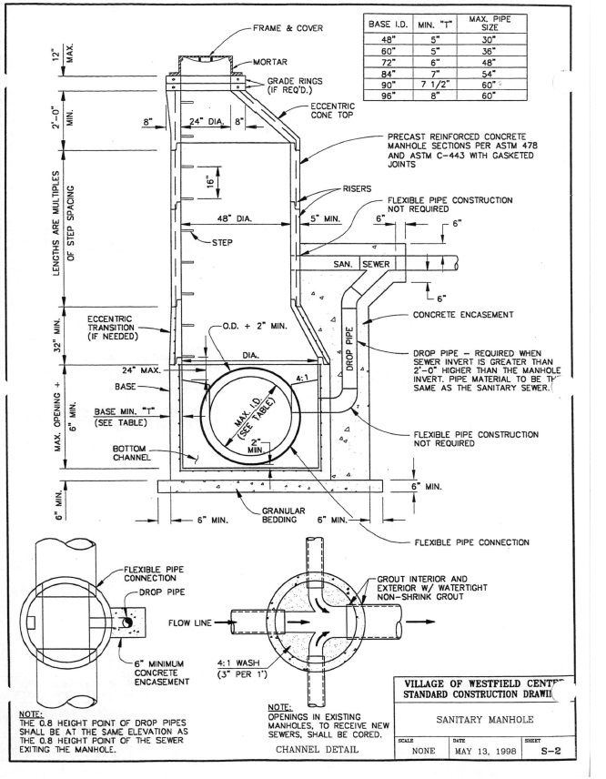
Manholes - ODOT 604
Manhole - Precast Reinforced Concrete ODOT 706.13
Castings - Gray or Ductile Iron - ODOT 711.12 or ODOT 711.13
Heavy Duty (Pavement Areas) - East Jordan Iron Works 1058 or approved equal with solid cover, machined bearing surfaces and “STORM SEWER” cast in the cover
Light Duty (Non-Pavement Areas) - East Jordan Iron Works 1022 or approved equal with solid cover, machined bearing surfaces and “SANITARY SEWER” cast in the cover
Steps - Reinforced Propylene Plastic Manhole Steps - ODOT 711.31 M.A. Industries, Inc. Model PS1-PF or approved equal
Flexible Pipe Connections
National Pollution Control Systems, Inc. KOR-N-SEAL
A-LOK Corporation A-LOK Manhole Seals
Thunderline Corporation Link-Seal
Sanitary Pressure Pipe - ODOT 748.02 (ASTM D2241-SDR26)
3" Diameter Minimum
Gray or Ductile Fittings - ODOT 748-01 - mechanical joints
Thrust Restraint - ODOT - 638
Restrained Joints - 748.01
Pipe Joints - EBAA Iron Series 1600 restrainers or approved equal
Fitting Joints - EBAA Iron Series 2000 PV restrainers or approved equal
Tracer Tape - ODOT 638
Reef Industries, Inc. Terra Tape Sentry Line 1350 or approved equal three (3) inch wide orange metalized foil tape imprinted with black lettering “CAUTION BURIED SEWER LINE”
Testing
Manhole Vacuum Testing - Appendix A
Sanitary Sewer Leakage Testing - Appendix B
Sanitary Sewer Deflection Testing - Appendix C
Sanitary Sewer Visual Inspection - Appendix D
Sanitary Pressure Pipe Leakage Testing - Appendix F
Residential/Small Commercial Sanitary Pump Station
Prefabricated concrete or fiberglass pump station with duplex automatically alternating
submersible pumps and dual rail design guide rails, NEMA 3R or 4X control panel with
battery backed up alarm light and horn to indicate high water level and seal failure, HOA
switches, and elapsed time meters. Myers or approved equal.
APPENDIX A
MANHOLE VACUUM TESTING
MANHOLE VACUUM TESTING
A vacuum test shall be performed upon all newly installed manholes. Testing shall be performed after installation of the top precast manhole section and prior to installation of the manhole frame or any precast adjusting rings.
All pipes entering the manhole shall be closed with airtight bulkheads or plugs and the top opening of the manhole shall be closed with a suitable airtight test head. Air shall be withdrawn from the manhole by means of a vacuum pump until a vacuum of ten (10) inches of mercury exists within the manhole. The vacuum line shall be valve closed and the time shall be measured for the vacuum in the manhole to drop from ten (10) to nine (9) inches of mercury.
The permissible time for the specified vacuum drop shall be greater than 1.77 seconds per foot of manhole depth for forty-eight (48) inch diameter manholes, 2.30 seconds per foot of manhole depth for sixty (60) inch diameter manholes and 2.84 seconds per foot of manhole depth for seventy-two (72) inch diameter manholes. If any manhole test discloses a time less than required, the contractor shall locate and repair the cause of the leakage until the test time falls within the permissible allowance.
The contractor shall supply all necessary apparatus for performing the required vacuum testing and shall conduct the testing in the presence of a Village of Westfield Center authorized representative.
APPENDIX B
SANITARY SEWER LEAKAGE TESTING
SANITARY SEWER LEAKAGE TESTING
A low pressure air test shall be performed upon all newly installed sanitary sewers. Testing shall not be performed until all laterals required on the line to be tested have been installed.
The ends of the sewer section to be tested shall be closed at the upstream and downstream manholes with airtight bulkheads or plugs. Air shall be added to the sewer by means of an air pump until a pressure of approximately four (4) pounds per square inch greater than the external water pressure exists within the sewer. The air line shall be valved closed and the pressure shall be allowed to stabilize for a period of at least two (2) minutes. After the stabilization period, the pressure in the line shall be reduced to 3.5 pounds per square inch greater than the external water pressure and the time shall be measured for the pressure in the sewer to drop from 3.5 to 2.5 pounds per square inch greater than the external water pressure.
The permissible time for the specified pressure drop shall be greater than the sum of the times for the various pipe sizes and lengths in the section being tested as determined by the following table:
MINIMUM TEST TIME FOR VARIOUS PIPE SIZES
Nominal Pipe Size (Inches) | Time Sec./100 Ft. | Nominal Pipe Size (Inches) | Time Sec./100 Ft. |
Nominal Pipe Size (Inches) | Time Sec./100 Ft. | Nominal Pipe Size (Inches) | Time Sec./100 Ft. |
6 | 40 | 24 | 214 |
8 | 71 | 27 | 250 |
10 | 89 | 30 | 286 |
12 | 107 | 33 | 323 |
15 | 125 | 36 | 361 |
18 | 144 | 42 | 436 |
21 | 178 | 48 | 513 |
If any sewer test discloses a time less than required, the contractor shall locate and repair the cause of the leakage until the test time falls within the permissible allowance.
The contractor shall supply all necessary apparatus for performing the required low pressure air testing and shall conduct the testing in the presence of a Village of Westfield Center authorized representative.
APPENDIX C
SANITARY SEWER DEFLECTION TESTING
SANITARY SEWER DEFLECTION TESTING
Deflection testing shall be performed on all newly installed sanitary sewers. Testing shall not be performed during the first thirty (30) days after the final backfill has been placed. Deflection testing shall be performed with electronic equipment specifically designed for sewer deflection testing and which will measure and continuously record both the location and pipe deflection. This equipment shall be approved by the engineer prior to use. The deflection sensing device shall be pulled through the sewer segment under test at a rate of speed not exceeding thirty (30) feet per minute.
The permissible deflection shall not exceed five (5) percent of the original inside diameter of the sewer. If any piping test discloses deflection greater than this amount, the contractor shall locate and repair the cause of the over deflection until the deflection, after a thirty (30) day period, falls within the permissible deflection.
The contractor shall supply all necessary apparatus for performing the required deflection testing and shall conduct the testing in the presence of a Village of Westfield Center authorized representative.
APPENDIX D
VISUAL INSPECTION
VISUAL INSPECTION
Visual inspection shall be performed upon all newly installed sanitary sewers. Inspection shall be performed after successful deflection testing by continuous closed circuit televising and video taping of the interior of sewer pipe between consecutive manholes. Inspection shall be performed by a qualified firm approved by the Village of Westfield Center.
Televising and videoing shall provide a clear and visible picture of the full interior diameter of the pipe. Video shall provide proper identification and the location of the sewers taped including a log showing the exact position of the television camera between manholes. Two (2) copies of the video shall be furnished to the Village of Westfield Center for review upon completion of the visual inspection.
The contractor shall supply all necessary equipment and apparatus for performing the visual inspection and the inspection shall be performed in the presence of a Village of Westfield Center authorized representative. Any defects such as cracked pipe, sags, joint leakage, etc. discovered as a result of the visual inspection shall be repaired to the satisfaction of the Village of Westfield Center and the repaired area shall be re-inspected after thirty (30) days.
APPENDIX E
BACKFLOW PREVENTION
BACKFLOW PREVENTION
There shall be no connection between the distribution system and any pipes, pumps, hydrants or tanks whereby unsafe water or other contaminating materials may be discharged or drawn into the system.
Individual water systems are prohibited from being interconnected to public water supply systems unless appropriate backflow prevention devices are used and plan approval is obtained from the Ohio EPA, Division of Public Water Supply and the Village of Westfield Center.
APPENDIX F
SANITARY PRESSURE PIPE LEAKAGE TESTING
SANITARY PRESSURE PIPE LEAKAGE TESTING
A hydrostatic leakage test shall be performed upon all newly installed PVC plastic pressure sewer piping. Testing shall not be performed until all laterals required on the line to be tested have been installed from the main pressure sewer to and including the curb stop. Testing shall be continuous through construction and at no time during construction shall there be more than 1,500 feet untested.
Hydrostatic testing shall be performed at a test pressure of sixty-five (65) pounds per square inch at the lowest point of the piping under test. Prior to applying the test pressure, the piping under test shall be fully completed, the piping shall be filled with water and all air shall be expelled from the piping. The piping shall be brought up to test pressure by means of a pump taking suction from a container from which volume of water added to the pipe can be determined. The test pressure shall be maintained for a period of two (2) hours through continuous pump operation. The quantity of water required to maintain the test pressure shall be accurately determined for the two (2) hour period and this quantity shall be multiplied by twelve (12) to obtain the leakage per twenty-four (24) hours.
The permissible leakage shall not exceed a rate of ten (10) gallons per twenty-four (24) hours per mile of pipe per inch of pipe diameter at the specified test pressure. If any piping test discloses leakage greater than this amount, the contractor shall locate and repair the cause of the leakage until the leakage falls within the permissible allowance. All visible leaks regardless of the amount shall be repaired.
The contractor shall supply the pump, pipe, connections all other necessary apparatus for performing the required hydrostatic leakage testing and shall conduct the testing in the presence of a Village of Westfield Center authorized representative.
The contract shall clean up the site and leave the same in a neat and clean condition at least equal in appearance to that which existed prior to the star of the work. All surplus material, refuse and debris shall be removed from the site and properly disposed of to the satisfaction of the engineer.
VILLAGE OF WESTFIELD CENTER, OHIO
STANDARD CONSTRUCTION DRAWINGS
General
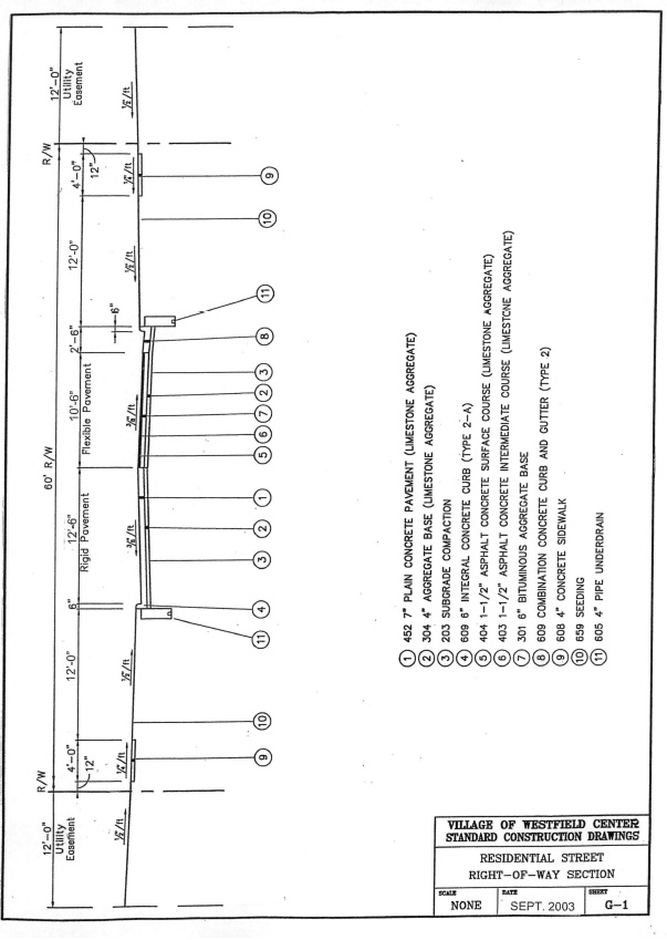
Right-of-way section - residential street G-1
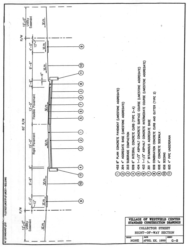
Right-of-way section - collector street G-2
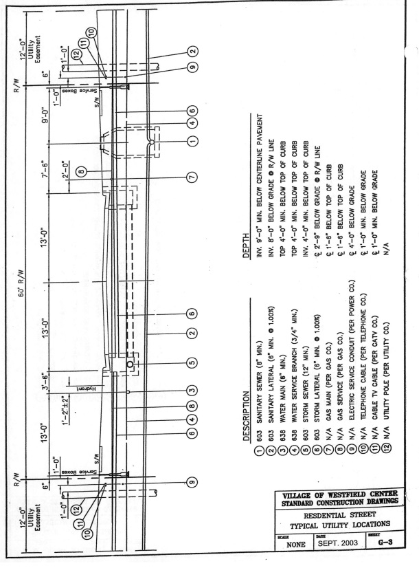
Utility locations - residential street G-3
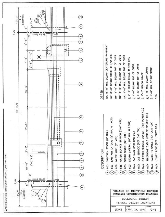
Utility locations - collector street G-4
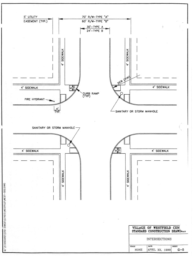
Intersections G-5
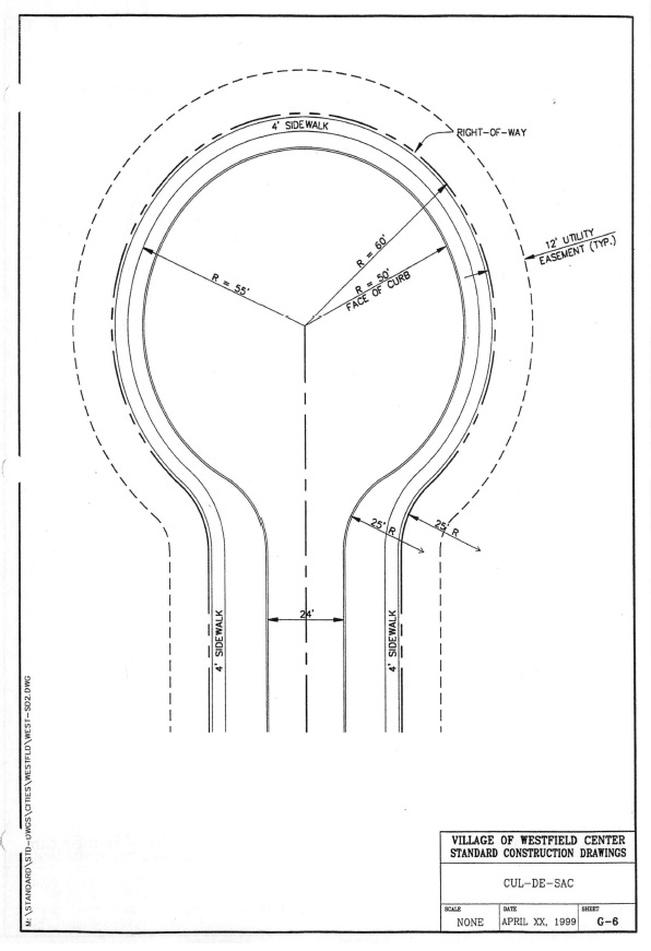
Cul-de-sacs G-6
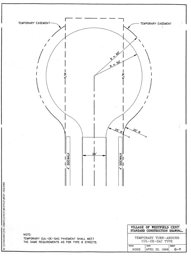
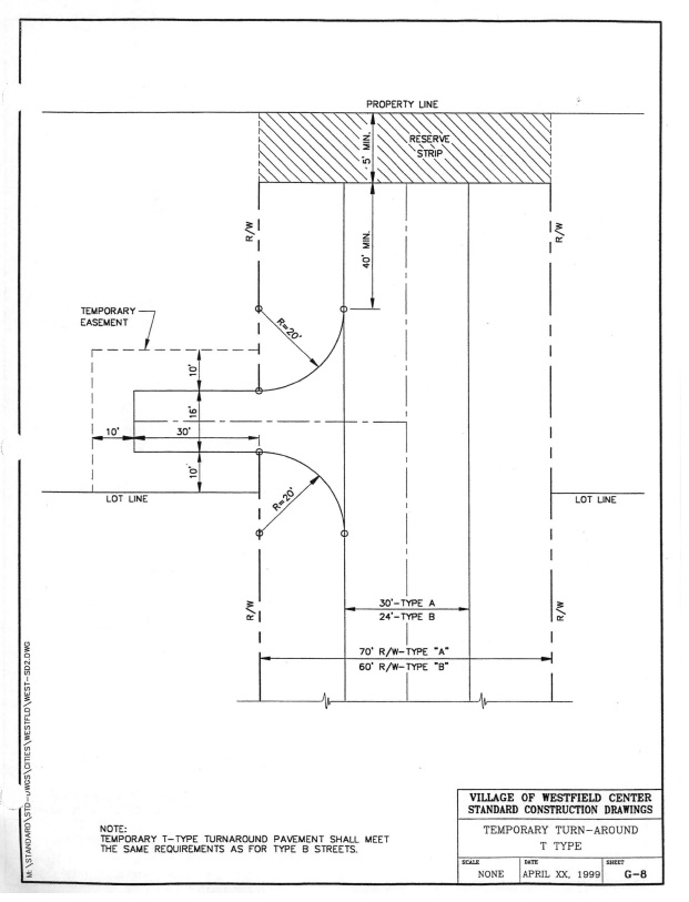
Temporary turn-around - cul-de-sac type G-7
Temporary turn-around - T type G-8
Pavement
Curbs P-1
Pavement under-drains P-2
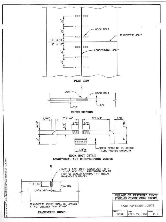
Rigid pavement joints P-3
Roadside
Driveways R-1
Sidewalks R-2
Sidewalk Curb Ramps R-3
Storm
Storm sewer trench ST-1
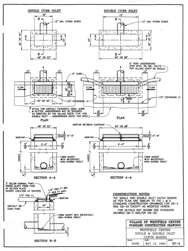
Dalton single & double inlet catch basins ST-2
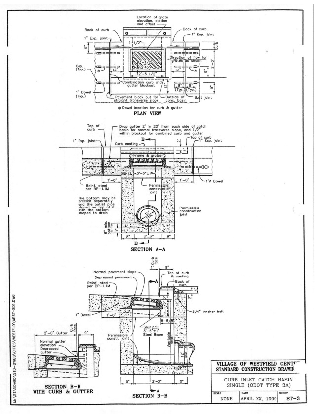
Curb inlet catch basin - single ST-3
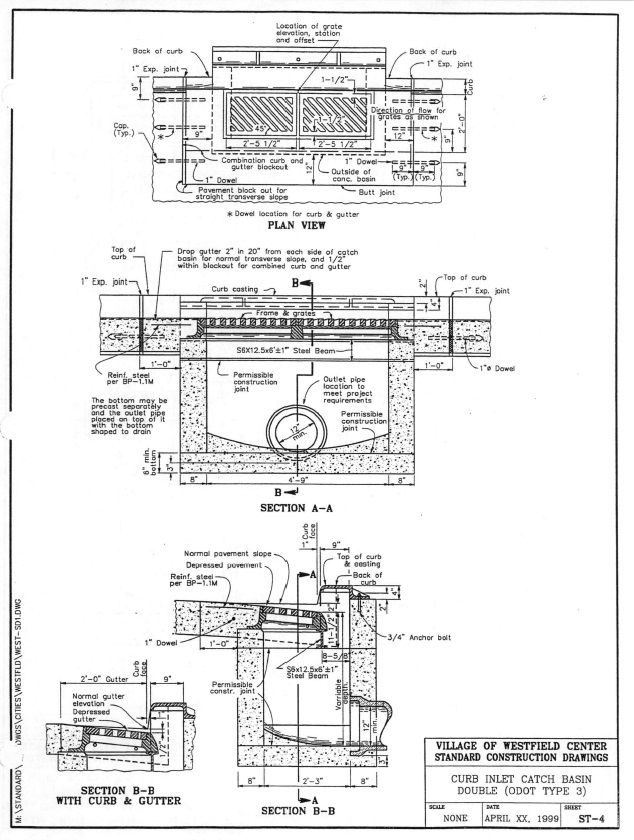
Curb inlet catch basin - double ST-4
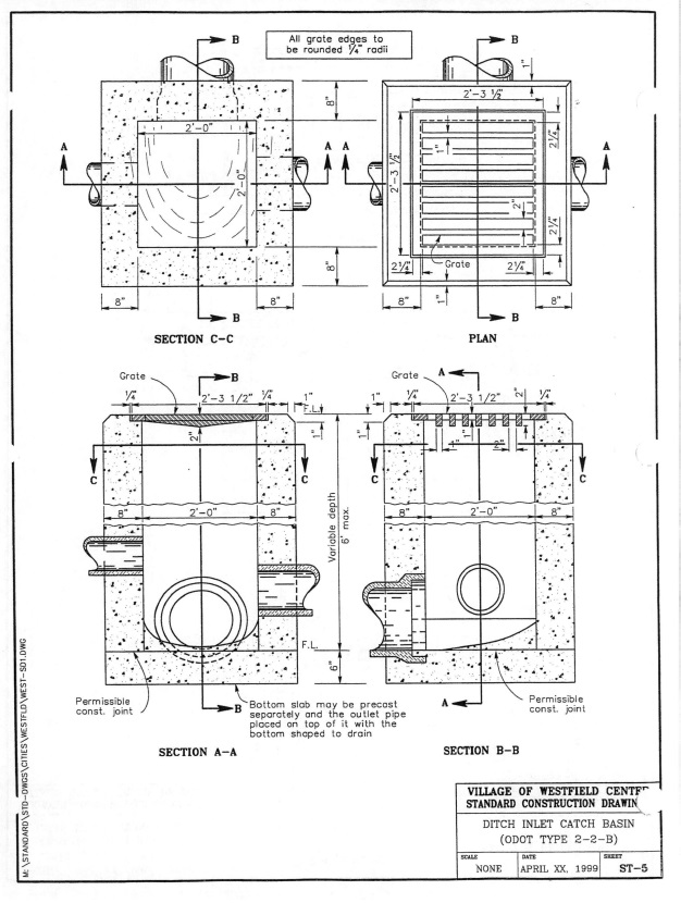
Ditch inlet catch basin ST-5
Storm manhole ST-6
Storm laterals ST-7
Sanitary
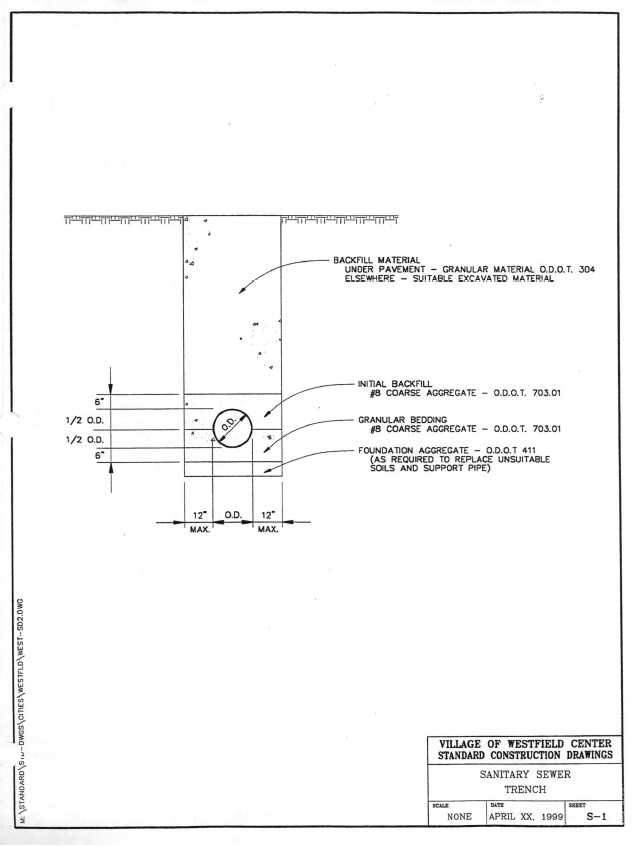
Sanitary sewer trench S-1
Sanitary manhole S-2
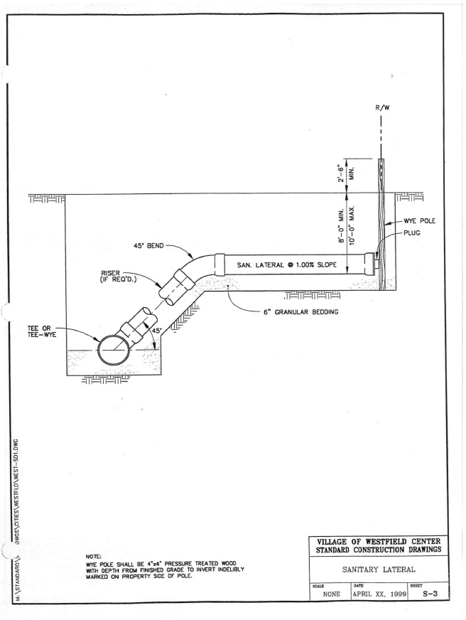
Sanitary laterals S-3
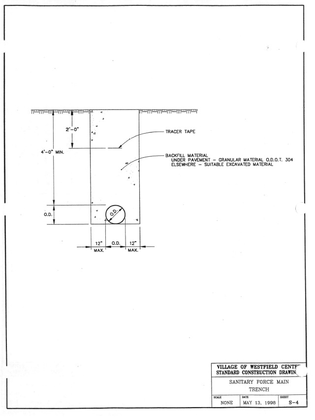
Force main trench S-4
Streetlight
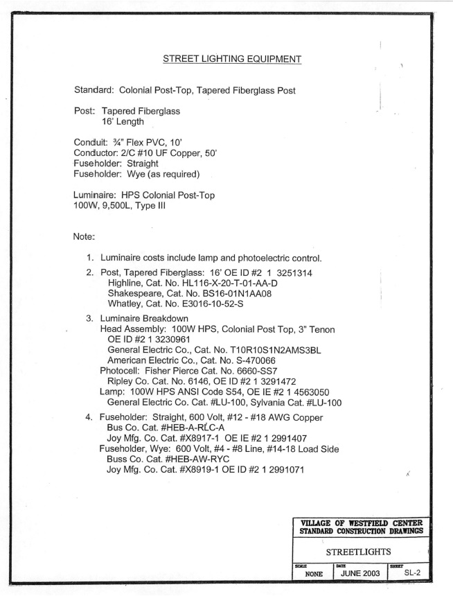
Spacing - details SL-1
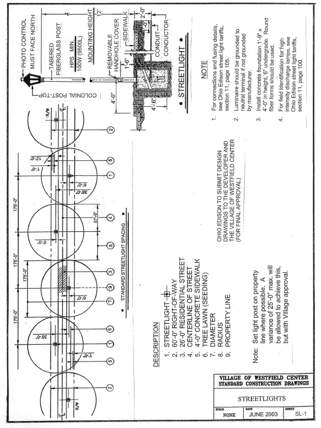
Lighting equipment SL-2