(A) General requirements.
(1) The applicant shall take all actions necessary to extend or create a water-supply district for the purpose of providing a water-supply system capable of providing for domestic water use and fire protection.
(2) Where a public water main is accessible, the subdivider shall install a complete water distribution system approved by the State Board of Health, including a connection for each lot.
(3) Water main extensions shall be approved by the officially designated agency of the state, county or municipality concerned.
(4) To facilitate the above, the location of all fire hydrants, water supply improvements, and the boundary lines of proposed districts indicating all improvements proposed to be served, shall be shown on the preliminary plat, and the cost of installing same shall be Included in the performance bond to be furnished by the subdivider.
(B) Individual wells and central water systems.
(1) In low-density zoning districts, if a public water system is not available, at the discretion of the Commission, each lot may be provided with an individual water supply, provided that the supply is installed in accordance with the minimum requirements of the State Board of Health. Water sample test results shall be submitted to the Health Department for its approval, and individual wells and central water systems shall be approved by the appropriate health authorities. These approvals shall be submitted to the Commission.
(2) If the Commission requires that a connection to a public water main be eventually provided as a condition for approval of an individual well or central water system, the applicant shall make arrangements for future water service at the time the plat receives secondary approval. Performance or cash bonds maybe required to ensure compliance.
(C) Fire hydrants. Hydrants should be provided at each street intersection and at intermediate points between intersections, meeting the requirements of the city and the Fire Insurance Underwriters' Association. Generally, hydrant spacing may range from 350 to 600 feet depending on the nature of the area being served, as determined by the City Engineer.
(D) Specifications for parts and materials.
(1) The water main shall be constructed out of ductile iron with slip joints, Class 50 or Class 350. The city will set the sizing on the water main, and must approve the water main before installation.
(2) The water main fittings shall be constructed out of ductile iron with mechanical joints, Class C153. The city must approve the fittings before installation.
(3) All water main valves must be true resilient wedge valves, open left. The city must approve the valves before installation.
(4) Hydrants must open left, with VA operating nuts. Depth is dependent on grade. Hydrants must be Kennedy or Mueller Brand. The city must approve the hydrants before installation.
(5) Water service lines:
(a) Copper lines must be K-type, coil or ridged. The city must approve the lines before installation; and
(b) PVC/Plastic lines must be nominal size, 200 pounds tested. The city must approve the lines before installation.
(6) Water meters are supplied by the utility, included in the cost of the water tap. The size is dependent on the amount of water used or line size.
(7) Water valve box, curb box and extension must be iron, and approved by the city before installation.
(8) Water meter pits must be constructed of PVC or approved by the city before installation.
(9) Fittings for meters and services lines must be brass, compression and flair.
(10) It is recommended to use a ball valve for inside valves in a home, business or industry.
(11) The back flow device must be state approved, and be approved by the city before installation. It must be tested at least one time per year by a certified tester.
(E) Inspection, handling and storage.
(1) Material standards and material selection.
(a) Pipe, fittings, valves and fire hydrants shall conform to the latest standards issued by the AWWA, if the standards exist, and be acceptable to the reviewing authority.
(b) In the absence of the standards, materials meeting applicable product standards and acceptable to the reviewing authority may be selected.
(c) Special attention shall be given to selecting pipe materials which will protect against both internal and external pipe corrosion.
(2) Joints.
(a) Packing and jointing materials used in the joints of pipe shall meet the standards of the AWWA and the reviewing authority.
(b) Pipe having mechanical joints or slip-on joints with rubber gaskets is preferred.
(3) Handling and storage.
(a) All pipe, fittings, valves, hydrants and accessories shall be loaded and unloaded by lifting with hoists or skidding in order to avoid shock or damage.
(b) Under no circumstances shall the materials be dropped.
(c) Pipe handled on skidways shall not be rolled or skidded against pipe on the ground.
(d) Slings, hooks or pipe tongs shall be padded and used in such a manner as to prevent damage to the exterior surface or internal lining of the pipe.
(e) Storage:
1. Materials, if stored, shall be kept safe from damage;
2. The interior of all pipe, fittings and other appurtenances shall be kept free from dirt or foreign matter at all times; and
3. Valves and hydrants shall be drained and stored in a manner that will protect them
(f) Pipe shall not be stacked higher than the limits shown in Table 4-2 above.
1. The bottom tier shall be kept off the ground on timbers, rails or concrete.
2. Pipe in tiers shall be alternated: bell, plain end; bell, plain end.
3. At least two rows of timbers shall be placed between tiers, and chocks shall be affixed to each timber in order to prevent movement.
4. The timbers shall be large enough to prevent contact between the pipe in adjacent tiers.
(g) Gaskets for mechanical and push-on joints shall be stored in a cool location out of direct sunlight.
1. Gaskets shall not come in contact with petroleum products.
2. Gaskets shall be used on a first-in, first-out basis.
(h) Mechanical-joint bolts shall be handled and stored in a dry location in a manner that will ensure proper use with respect to types and sizes.
(i) Prolonged exposure to sunlight will eventually deteriorate polyethylene film.
1. Therefore, the exposure prior to backfilling the wrapped pipe should be kept to a minimum.
2. If several weeks of exposure prior to backfilling are anticipated, Class C material should be used.
(F) Trench construction/grade and alignment.
(1) Trench construction. The trench shall be excavated to the alignment, depth and width specified or shown on the plans and shall be in conformance with all federal, state and local regulations for the protection of the workers.
(a) Trench preparation shall proceed in advance of pipe installation only as far as stated in the specifications or as directed by the owner.
(b) Discharge from any trench-dewatering pumps shall be conducted to natural drainage channels, storm sewers or as directed by applicable regulatory agencies.
(c) Excavated material shall be placed in a manner that will not obstruct the work nor endanger the workers or the public, or obstruct sidewalks, driveways, roadways or other structures. Placement of excavated material shall be done in compliance with federal, state and local regulations.
(d) Pavement removal:
1. Removal of pavement and road surfaces shall be a part of the trench excavation;
2. The amount removed shall depend on the width of trench required for installation of the pipe and the dimensions of the area into which valves, hydrants, specials, manholes and other structures by more than six inches (150 mm) in any direction, unless otherwise required or approved by the owner; and
3. Methods such as sawing, drilling or chipping shall be used to ensure the breakage of pavement along straight lines.
(e) Width:
1. The width of the trench at the top of the pipe shall be the same as that afforded by the single-pass capabilities of normally available excavating equipment and shall be ample to permit the pipe to be laid and joined properly and to allow the backfill to be placed as specified;
2. Trench widths shown in Table 4-2 may be used as a guide; and
3. Trenches shall be of an extra width, when required, to permit the placement of timber supports, sheeting, bracing and appurtenances as required by the safety requirements of the agency having jurisdiction.
(f) Bell holes:
1. Holes for the bells shall be provided at each joint, but shall be no larger than necessary to allow joint assembly and to ensure that the pipe barrel will lie flat on the trench bottom; and
2. Push-on type joints require only minimum depressions for bell holes
(g) Other than noted previously, the trench bottom shall be true and even to provide support for the full length of the pipe barrel, except that a slight depression may be provided to allow withdrawal of pipe slings or other lifting tackle without damaging coating or polyethylene encasement.
(h) Rock conditions:
1. When excavation of rock is encountered, all rock shall be removed to provide a clearance below and on each side of all pipe, valves and fittings of at least six inches (150 mm) for pipe sizes 24 inches or smaller and nine inches (230 mm) for pipe sizes 30 inches and larger; and
2. When excavation is completed, a layer of appropriate backfill material shall be placed on the bottom of the trench to the previously mentioned depths, leveled and tamped.
(i) These clearances and bedding procedures shall also be observed for pieces of concrete or masonry and other debris or subterranean structures, such as masonry walls, piers or foundations, that may be encountered during excavation.
(j) This installation procedure shall be followed when gravel formations containing loose boulders greater than approximately eight inches (200 mm) in diameter are encountered.
(k) In all cases, the specified clearances should be maintained between the bottom of all pipe and appurtenances and any part, projection or point of rock, boulder or stone of sufficient size and placement that, in the opinion of the owner, could cause a fulcrum point or pointload.
(2) Alignment and grade
(a) The water mains shall be laid and maintained to lines and grades established by the plans and specifications, with fittings, valves, tapped or boosed outlets, and hydrants at the required locations unless otherwise approved by the owner.
(b) Valve-operating stems shall be oriented in a manner to allow proper operation.
(c) Hydrants shall be installed plumb.
(d) Prior investigation:
1. Prior to excavation, investigation shall be made to the extent necessary to determine the location of existing underground structures and conflicts.
2. Care shall be exercised by the contractor during excavation to avoid damage to existing structures.
3. Special precautions shall be taken when the water main being installed is adjacent to a facility that is cathodically protected.
(e) When obstructions that are not shown on the plans are encountered during the progress of work and interfere so that an alteration of the plans is required, the owner will alter the plans, or order a deviation in line and grade, or arrange for removal, relocation or reconstruction of the obstructions.
(f) When crossing existing pipelines or other structures, alignment and grade shall be adjusted as necessary, with the approval of owner, to provide clearance as required by federal, state and local regulations or as deemed necessary by the owner to prevent future damage or contamination of either structure.
(g) Should the trench pass over a sewer or other previous excavation, the trench bottom shall be sufficiently compacted to provide support equal to that of the native soil or to conform to other regulatory requirements in a manner that will prevent damage to the existing installation.
(h) Blasting:
1. Blasting for excavation shall be permitted only after securing the approval of the owner, who will establish the hours of blasting; and
2. The blasting procedure, including protection of persons and property, shall be in strict accordance with federal, state and local regulations.
(i) Trees, shrubs, fences and all other property and surface structures shall be protected during construction, unless their removal is shown in the plans and specifications or approved by the owner.
(j) Any cutting of tree roots or branches shall be done only as approved by the owner.
(k) Temporary support, adequate protection and maintenance of all underground and surface structures, drains, sewers and other obstructions encountered in the progress of the work shall be provided in accordance with specifications or applicable regulations.
(l) All properties that have been disturbed shall be restored as nearly as practical to their original condition.
(m) Unsuitable subgrade material.
1. When the subgrade is found to include ashes, cinders, refuse organic material, or other unsuitable material, the material shall be removed to a minimum of at least six inches (150 mm) below the bottom of the pipe or to the depth ordered by the owner.
2. The removed material shall be replaced, under the direction of the owner, with clean, stable backfill material.
(n) When the bottom of the trench or the subgrade is found to consist of material that is unstable to such a degree that, in the judgement of the owner, it cannot be removed, a foundation for the pipe and/or appurtenance shall be constructed using piling, treated timber, concrete or other materials, at the direction of the owner.
(o) Appropriate traffic-control devices shall be provided in accordance with federal, state and local regulations to regulate, warn and guide traffic at the work site.
(G) Pipe installation.
(1) Proper implements, tools and facilities shall be provided and used for the safe and convenient performance of the work.
(a) All pipe, fittings, valves and hydrants shall be lowered carefully into the trench by means of a derrick, ropes or other suitable tools or equipment, in such a manner as to prevent damage to water main materials and protective coatings and lining.
(b) Under no circumstances shall water main materials be dropped or dumped into the trench.
(c) Where practical, the trench should be dewatered prior to installation of the pipe.
(2) Examination of material:
(a) All pipe, fittings, valves, hydrants and other appurtenances shall be examined carefully for damage and other defects immediately before installation; and
(b) Defective materials shall be marked and held for inspection by the Waterworks Superintendent, who may prescribe corrective repairs or reject the materials.
(3) Pipe ends:
(a) All lumps, blisters and excess coating shall be removed from the socket and plain end of each pipe; and
(b) The outside of the plain end and the inside of the bell shall be wiped clean and dry and be free from dirt, sand, grit or any foreign materials before the pipe is laid.
(4) Pipe cleanliness:
(a) Foreign material shall be prevented from entering the pipe while it is being placed in the trench; and
(b) No debris, tools, clothing or other materials shall be placed in the pipe at any time.
(5) Pipe placement:
(a) As each length of pipe is placed in the trench, the joint shall be assembled and the pipe brought to correct line and grade; and
(b) The pipe shall be secured in place with approved backfill.
(6) Pipe plugs:
(a) At times when pipe-laying is not in progress, the open ends of pipe shall be closed by a water-tight plug or other means approved by city waterworks;
(b) The plug shall be fitted with a means for venting;
(c) When practical, the plug shall remain in place until the trench is pumped completely dry; and
(d) Care must be taken to prevent pipe flotation, should the trench fill with water.
(7) For any installation requiring polyethylene encasement for ductile-iron pipe, the encasement shall be installed in accordance with ANSI/AWWA C105/A21.5.
(8) Parallel installation:
(a) Water main must be laid at least ten feet horizontally from any existing or proposed sewage line.
1. The distance shall be measured edge to edge.
2. In a case where it is not practical to maintain a ten-foot separation, the reviewing authority may allow deviation on a case-by-case basis, if supported by data from the design engineer.
(b) The deviation may allow installation of the water main closer to a sewer, provided that the water main is laid in a separate trench or on an undisturbed earth shelf located on one side of the sewer at such an elevation that the bottom of the water main is at least 18 inches above the top of the sewer.
(9) Water mains crossing sewers shall be laid to provide a minimum vertical distance of 18 inches between the outside of the water main and the outside of the sewer.
(a) This shall be the case where the water main is either above or below the sewer.
(b) At crossing, one full length of water pipe shall be located so both joints will be as far from the sewer as possible.
(c) Special structural support for the water and sewer pipes may be required.
(10) No water pipe shall pass through or come in contact with any part of a sewer manhole.
(11) Joint assembly:
(a) Push-on joints shall be assembled in accordance with prevailing city standards; and
(b) Mechanical joints shall be assembled in accordance with prevailing city standards.
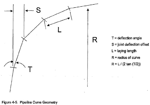
(a) The deflections listed are maximum deflections and should not be exceeded.
(b) For design purposes, deflection should be limited to 80% of the values shown.
(c) Figure 4-5 illustrates the maximum offset S and approximate radius curve R, which are listed in Tables 4-4 and 4-5.
(13) Cutting pipe for insertion of valves, fittings or closure pieces shall be done in conformance with all safety recommendations of the manufacturer of the cutting equipment.
(a) Cutting shall be done in a safe, workmanlike manner without creating damage to pipe or cement-mortar lining.
(b) Existing gray-iron pipe may be cut using a hydraulic squeeze cutter, abrasive pipe saw, rotary wheel cutter, guillotine pipe saw or milling wheel saw.
(14) Ductile-iron pipe may be cut using an abrasive pipe saw, milling wheel saw, rotary wheel cutter or guillotine pipe saw. Cut ends and rough edges shall be ground smooth, and for push-on joint connections the cut end shall be beveled by methods recommended by the manufacturer and approved by city waterworks.
(H) Valves and fitting installation.
(1) Examination of material.
(a) Prior to installation, valves shall be inspected for direction of opening, number of turns to open, freedom of operation, tightness, pressure-containing bolting and test plug, cleanliness of valve ports and especially seating surfaces, handling damage and cracks.
(b) Defective valves shall be corrected and/or held for inspection by city waterworks.
(c) Valves shall be closed before being installed.
(2) Valve location.
(a) Valves in water mains shall, where practical, be located within or immediately adjacent to the street property lines.
(b) Sufficient valves shall be provided on a water main so that inconvenience and sanitary hazards will be minimized during repairs.
(c) Valves should be located at not more than 500-foot intervals in commercial districts and at not more than one block or 800-foot intervals in other districts.
(d) Main shall be drained through drainage branches or blowoffs.
(e) Drainage branches, blowoffs, air vents and appurtenances shall be provided with control valves and shall be located and installed in accordance with prevailing city standards.
(f) Drainage branches or blowoffs should not be directly connected to any storm or sanitary sewer, submerged in any stream, or be installed in any other manner that will permit back siphonage into the distribution system.
(3) Valve protection and box. A valve box or a vault shall be provided for every valve.
(a) A valve box shall be provided for every valve that has no gearing or operation mechanism or in which the gearing or operation mechanism is fully protected with a gear case.
(b) The valve box shall not transmit shock or stress to the valve.
(c) The valve box shall be centered over the operating nut of the valve, with the box cover flush with the surface of the finished area or such other level as may be directed by city waterworks.
(4) Valve vault. A valve vault designed to prevent settling on the pipe shall be provided for every valve that has exposed gearing or operating mechanisms.
(a) The operating nut shall be readily accessible for operation through the opening in the valve vault, which shall be set flush with the surface of the finished pavement or such other level as may be specified.
(b) Vaults shall be constructed to permit minor valve repairs and to protect the valve and pipe from impact where they pass through the vault walls.
(c) In no case shall valves be used to bring misaligned pipe into alignment during installation.
(d) Pipe shall be supported in such a manner as to prevent stress on the valve.
(5) Plugs and caps. All dead ends on new mains shall be closed with plugs or caps that are suitably restrained to prevent blowing off under test pressure. If a blowoff-valve precedes a plug or cap, it too shall be equipped with suitable blowoff facilities.
(6) Resilient wedge valves. All valves for the distribution system shall be resilient wedge valves. The series, type and make must be approved by city waterworks before installation.
(I) Hydrant installation.
(1) Prior to installation. Prior to installation, all hydrants shall be inspected for direction of opening, nozzle threading, operating-nut and cap-nut dimensions, tightness of pressure-containing bolting, cleanliness of inlet elbow, handling damage and cracks. Defective hydrants shall be corrected or held for inspection by the city waterworks.
(2) Placement. All hydrants shall stand plumb and shall have their nozzles parallel with or at right angles to the curb, except that hydrants shall be installed such that hydrants having two-hose nozzles 90 degrees apart shall be set with each nozzle facing the curb at an angle of 45 degrees.
(a) Hydrants shall be set to the established grade, with the center line of the lowest nozzle at least 12 inches above the ground or as directed by the city waterworks.
(b) Traffic model hydrants shall be installed such that the break away flange shall be installed not less than two inches, nor more than six inches, above established grade.
(c) Each hydrant shall be connected to the main with a six-inch or larger diameter branch controlled by an independent valve, unless otherwise specified by city waterworks.
(d) The valve shall be restrained to allow shutoff when the hydrant is to be removed.
(3) Dry barrel hydrant. When a dry barrel hydrant is set in soil that is pervious, drainage shall be provided at the base of the hydrant by placing coarse gravel or crushed stone mixed with coarse sand from the bottom of the trench to at least six inches above the drain-port opening in the hydrant and to a distance of one foot around the elbow.
(a) Where ground water rises above the drain port or when the hydrant is located within eight feet of a sanitary sewer main, the drain port shall be plugged and water pumped from the hydrant when freezing may occur.
(b) When a dry barrel hydrant with an open drain port is set in clay or other impervious soil, a drainage pit two feet by two feet by two feet shall be excavated below each hydrant.
(c) The drainage pit shall be filled with coarse gravel or crushed stone mixed with coarse sand, under and around the elbow of the hydrant and to a level of six inches above the drain port.
(d) At no time should hydrant drains be connected to sanitary sewers or storm drains.
(4) Location and spacing of hydrants.
(a) Hydrants should be provided at each street intersection and at intermediate points between intersections as recommended by the state insurance service and city waterworks. Hydrant spacing may range from 350 to 600 feet depending on the area being served.
(b) Hydrant leads:
1. Hydrant leads shall be a minimum of six inches in diameter; and
2. Auxiliary valves shall be installed in all hydrant leads.
(c) Fire hydrants should have a bottom valve size of at least five inches, 1 four and one-half-inch pumper nozzle and 2 two and one-half-inch nozzles.
(d) In the case of hydrants that are intended to fail at the groundline joint upon vehicle impact (traffic hydrant), specific care must be taken to provide adequate soil resistance to avoid transmitting shock movement to the lower barrel and inlet connection. In loose or poor load-bearing soil, this may be accomplished by pouring a concrete collar approximately six inches thick to a diameter of two feet at or near the groundline around the hydrant barrel.
(e) Whether over or under water, surface water crossings present special problems. The reviewing authority should be consulted before final plans are prepared.
1. Above-water crossings. The pipe shall be adequately supported and anchored, protected from damage and freezing, and accessible for repair or replacement.
2. Under-water crossings. Minimum cover of two feet shall be provided over the pipe. When crossing water courses which are greater than 15 feet in width, the following shall be provided:
a. The pipe shall be of special construction, having flexible watertight joints;
b. Valves shall be provided at both ends of the water crossings so that the section can be isolated for testing or repair; and
c. The valve shall be easily accessible and not subject to flooding, and the valve closest to the supply source shall be in a manhole. Permanent taps shall be made on each side of the valve within the manhole to allow insertion of a small meter to determine leakage and for sampling purposes.
(f) Highway and railroad crossings:
1. Casing pipe.
a. When casing pipe is specified for highways or railroad crossings, the project shall be completed in accordance with applicable federal, state and local regulations.
b. In the case of railroad crossings, the project should also comply with regulations established by the railroad company.
c. General practice permits boring for casing diameters through 36 inches with maximum length of about 175 feet (53 m); jacking for diameters 30 inches through 60 inches with lengths of about 200 feet (61 m); and tunneling for pipes 48 inches and larger for longer lengths.
2. Carrier pipe.
a. The casing pipe should be six to eight inches (150-200 mm) larger than the outside diameter of the ductile-iron pipe bells.
b. Carrier pipe may be pushed or pulled through the completed casing pipe.
c. Chocks or skids should be placed under the carrier pipe to ensure approximate centering within the casing pipe and to prevent damage during installation.
d. Care must be exercised in order to avoid metal-to-metal contact.
e. In order to avoid the transfer of earth and live loads to the carrier pipe, the space between the carrier and casing pipes should not be filled completely.
(g) Flushing:
1. Where dead-end mains occur, they shall be provided with a fire hydrant if flow and pressure are sufficient, or with an approved flushing hydrant or blow-off for flushing purposes.
a. Flushing devices should be sized to provide flows which will give a velocity of at least two and one-half feet per second in the water main being flushed.
b. No flushing device shall be directly connected to any sewer.
2. Foreign material left in the pipelines during installation often results in a valve or hydrant seat leaking during pressure tests.
a. Every effort should be made to keep lines clean during installation.
b. Thorough flushing is recommended prior to a pressure test; flushing should be accomplished by partially opening and closing valves and hydrants several times under expected line pressure, with flow velocities adequate to flush foreign material out of the valves and hydrants.
3. Chambers, pits or manholes containing valves, blow-offs, meters or other appurtenances to a distribution system, shall not be connected directly to any storm drain or sanitary sewer, nor shall blow-offs or air relief valves be connected directly to any sewer. The chambers or pits shall be drained to the surface of the ground where they are not subject to flooding by surface water, or to absorption pits underground.
(h) Thrust restraint:
1. Hydrants. The bowl of each hydrant shall be well braced against a sufficient area of un-excavated earth at the end of the trench with stone slabs or concrete thrust blocks, or it shall be tied to the pipe with suitable metal tie rods, clamps or restrained joints, as shown or directed by the owner;
2. Fittings. All plugs, caps, tees, reducers and bends, unless otherwise specified, shall be provided with thrust blocks or suitably restrained joints, as shown or specified by the owner;
3. Design.
a. The design pressure is maximum pressure to which the pipeline will be subjected, with consideration given to the vulnerability of the pipe-soil system when the pressure is expected to be applied.
b. In most cases, this will be the test pressure of the pipe, applied shortly after installation, when the pipe-soil system is normally most vulnerable.
c. For buried pipelines, thrust restraint is achieved by transferring the thrust force to the soil structure outside the pipe.
d. The objective of the design is to distribute the thrust forces to the soil structure in such a manner that joint separation will not occur in unrestrained joints.
4. Concrete thrust blocks.
a. Vertical and horizontal thrust blocks shall be made of concrete having a compressive strength of not less than 2,000 psi (13.8 MPa) after 28 days.
b. The blocks shall be placed between solid ground, and fitting is to be anchored; the mass of the block and/or the area of bearing on the pipe and on the ground in each instance shall be that shown or directed by the owner.
c. The blocking shall, unless otherwise shown or directed, be so located as to contain the resultant thrust force in such a way that the pipe and fitting joints will be accessible for repair.
5. Restrained joints.
a. Restraining mechanisms for push-on or mechanical joints may be used instead of concrete backing, if so indicated in the plans and specifications.
b. Tie rods, clamps or other components of dissimilar metal shall be protected against corrosion by hand application of a suitable coating or by encasement of the entire assembly with eight mil (0.2 mm) loose polyethylene film in accordance with ANSI/AWWA C105/A21.5.
(i) Service taps:
1. Tapping.
a. Corporation stops may be installed either before or after pipe installation.
b. Generally, they are located at 10:00 or 2:00 on the circumference of the pipe and may be screwed directly into the tapped and treaded main without any additional appurtenances.
c. When more than one tap in an existing gray cast-iron pipe is necessary to deliver the required flow, the taps should be staggered around the circumference at least 12 inches (0.3 m) apart (not in a straight line).
d. Ductile-iron pipe in all classes may be directly tapped with standard corporation stops; however, torque requirement for the installation may be effectively reduced by the application of two layers of three mil (0.1 mm) TFE tape to the male threads of the corporation stop.
e. Service taps on gray cast-iron and ductile-iron mains encased in polyethylene may be accomplished by making an x-shaped cut in the polyethylene and temporarily folding back the film or by tapping directly through the polyethylene.
f. After the tap has been completed, cuts in the polyethylene and any other areas of damage to the film shall be repaired with tape as described in ANSI/AWWA C105/A21.5.
g. Service lines of dissimilar metals also shall be wrapped with polyethylene or a suitable dielectric tape for a minimum clear distance of three feet (0.9 m) away from the gray cast-iron or ductile-iron main.
2. Freezing. In this cold climate with deep frost penetration, freezing of service lines can be a problem.
a. In the localities, installing corporation stops horizontally at the 3:00 or 9:00 position on the pipe circumference will conserve available cover over the service line or reduce the necessary depth of bury on the main pipeline.
b. No service tap shall furnish water to two distance premises.
3. Persons taking water must protect the service tap, lines and main from freezing or damage.
(j) Hydrostatic testing; pressure and leakage test:
1. Test restrictions.
a. Test pressure shall not be less than one and one-quarter times the working pressure at the highest point along the test section.
b. Test pressure shall not exceed pipe or thrust-restraint design pressures.
c. The hydrostatic test shall be of at least two in duration.
d. Test pressure shall not vary by more than ± five psi (35 MPa or 0.35 bar) for the duration of the test.
e. Valves shall not be operated in either direction at differential pressure exceeding the rated value working pressure.
f. Use of a test pressure greater than the rated valve pressure can result in trapped test pressure between the gates of a double-disc gate valve.
g. For tests at these pressures, the test setup should include provision, independent of the valve, to reduce the line pressure to the rated value pressure on completion of the test.
h. The valve can then be opened enough to equalize the trapped pressure with the line pressure, or fully opened if desired.
i. Test pressure shall not exceed the rated pressure of the valves when the pressure boundary of the test section includes closed, resilient-seated gate valves or butterfly valves.
2. Pressurization.
a. After the pipe has been laid, all newly-laid pipe or any valved section thereof shall be subjected to a hydrostatic pressure of at least one and one-half times the working pressure at the point of testing.
b. Each valve section of pipe shall be slowly filled with water, and the specified test pressure, based on the elevation of the lowest point of the line or section under test and corrected to the elevation of the test gauge, shall be applied by means of a pump connected to the pipe in a manner satisfactory to the owner.
c. Valves shall not be operated in either the opening or closing direction at differential pressures above the rated pressure.
d. It is good practice to allow the system to stabilize at the test pressure before conducting the leakage test.
3. Air removal. Before applying the specified test pressure, air shall be expelled completely from the pipe, valves and hydrants.
a. If permanent air vents are not located at all high points, the contractor shall install corporation cocks at the ports so that the air can be expelled as the line is filled with water.
b. After all the air has been expelled, the corporation cocks shall be closed and the test pressure applied.
c. At the conclusion the pressure test, the corporation cocks shall be removed and plugged or left in place at the discretion of the owner.
4. Examination. Any exposed pipe, fittings, valves, hydrants and joints shall be examined carefully during the test.
a. Any damaged or defective pipe, fittings, valves, hydrants or joints that are discovered following the pressure test shall be repaired or replaced with sound material.
b. The test shall be repeated until it is satisfactory to the owner.
5. Leakage defined. LEAKAGE shall be defined as the quantity of water that must be supplied into the newly laid: pipe or any valved section thereof to maintain pressure within five psi (35 MPa or 0.35 bar) or the specified test pressure after the pipe has been filled with water and the air has been expelled. Leakage shall not be measured by a drop in pressure in a test section over a period of time.
6. Allowable leakage.
a. No pipe installation will be accepted if the leakage is greater than that determined by prevailing city standards.
b. When testing against closed metal-seated valves, an additional leakage per closed valve of 0.0078 gph/inch (0.0012 L/h/mm) of nominal valve size shall be allowed.
c. When hydrants are in the test section, the test shall be made against closed hydrant valves.
7. Acceptance of installation
a. Acceptance shall be determined on the basis of allowable leakage. If any test of laid pipe discloses leakage greater than that specified in Table 4-6, the contractor shall, at his or her own expense, locate and make approved repairs as necessary until the leakage is within the specified allowance.
b. All visible leaks are to be repaired, regardless of the amount of leakage.
(J) Backfilling.
(1) All backfill material shall be free from cinders, ashes, refuse, vegetable or organic material, boulders, rocks or stones, frozen soil or other material that, in the opinion of the owner, is unsuitable.
(2) From one foot (300 mm) above the top of the pipe to the subgrade of the pavement, material containing stones up to eight inches (200 mm) in their greatest dimension may be used, unless otherwise specified.
(3) When the type of backfill material is not indicated on the plans or is not specified, the excavated material may be used, provided that the materials consist of loam, clay, sand, gravel or other materials that, in the opinion of the owner, are suitable for backfilling.
(4) If excavated material is indicated on the drawings or specified for backfill, and there is a deficiency due to rejection of a part thereof, the required amount of sand, gravel or other approved material shall be provided.
(5) For purposes of definition:
(a) Sand is material graded from fine to coarse, containing less than 10%, by weight, of loam and clay, that passes a three-inch sieve with no more than 5%, by weight, remaining on a number four sieve.
(b) Gravel is a reasonably uniform combination containing no boulders or stone larger than two inches (50 mm) and not containing excessive amounts of clay and loam.
(c) Crushed stone is limestone or dolomite ledge-rock material that all passes a one-half-inch sieve with no more than 25% passing a number 100 sieve.
(6) When special backfill compaction procedures are required, they shall be accomplished in accordance with project specifications or applicable federal, state and local regulations.
(7) Partial backfilling during testing:
(a) Newly installed pipelines are normally tested after backfilling; and
(b) When unusual conditions require that pressure and leakage testing be accomplished before completion of backfilling or with pipe joints accessible for examination, sufficient backfill material shall be placed over the pipe and soil, should be backfilled prior to testing.
(8) If polyethylene encasement is used, any damage that occurs to the water main shall be repaired in accordance with ANSI/AWWA C105/A21.5.
(K) Disinfection.
(1) A newly installed main shall be disinfected in accordance with ANSI/AWWA C651. Following chlorination, the main should be flushed as soon as possible (within 24 hours), since prolonged exposure to high concentrations of chlorine might damage the asphaltic seal coating.
(2) All new, cleaned or repaired water mains shall be disinfected in accordance with AWWA Standard C601. The specifications shall include detailed procedures for the adequate flushing, disinfection and microbiological testing of all water mains.
(L) Cross-connections and interconnections.
(1) Cross-connections. There shall be no connection between the distribution system and any pipes, pumps, hydrants or tanks whereby unsafe water or other contaminating materials may be discharged or drawn into the system.
(2) Cooling water. Neither stream condensate nor cooling water from engine jackets or other heat exchange devices shall be returned to the potable water supply.
(3) Interconnections. The approval of the reviewing authority shall be obtained for interconnections between potable water supplies.
(4) Water services and plumbing.
(a) Plumbing. Water services and plumbing shall conform to relevant local and/or state plumbing codes, or to the National Plumbing Code.
(b) Booster pumps. Individual booster pumps shall not be allowed for any individual service from the public water supply mains.
(M) Cross-connections, control, operation; definitions. For the purpose of this section, the following definitions shall apply unless the context clearly indicates or requires a different meaning.
AIR GAP. An unobstructed vertical distance through atmosphere between the discharge end of a pipeline supplied from a public water supply, and the overflow rim of the receiving portion of the customer water system.
BACKFLOW. The flow of contaminants into the public water supply distribution system from a source other than the public water supply.
BOOSTER PUMP. A pump installed on a pipeline to increase water pressure and flow.
CROSS-CONNECTION. Any physical arrangement, including cross-connection control devices not in working order, whereby a public water supply distribution system is directly connected, either continuously or intermittently, with any secondary source of supply, sewer, drain, conduit, pool, piping, storage, reservoir, plumbing fixture or other device which contains, or may contain, and is capable of imparting to the public water supply, contaminants, contaminated water, sewage or liquid of unknown or unsafe quality.
CROSS-CONNECTION CONTROL DEVICE. Any device or assembly, approved by the board for construction on or installation in water supply piping, which is capable of preventing contaminants from entering the public water supply distribution system.
CROSS-CONNECTION CONTROL DEVICE INSPECTOR. A person who has successfully completed training in testing and inspection of cross-connection control devices at an agency or school acceptable to the commissioner, who has registered with the commissioner, and who has not been notified by the commissioner that his or her work is unacceptable under this rule (327 I.A.C. 8-10).
CROSS-CONNECTION HAZARD. Any customer facility which, because of the nature and extent of activities on the premises or the materials used in connection with the activities or stored on the premises, would present an immediate or potential danger or health hazard to customers of the public water supply should backflow occur.
CUSTOMER. Any person who receives water from a public water supply.
CUSTOMER SERVICE LINE. The pipeline from the public water supply to the first tap, fixture, receptacle or other point of customer water use; or the first secondary source of supply, or pipeline branch in a building.
CUSTOMER WATER SYSTEM. All piping, fixtures and appurtenances, including secondary sources of supply, used by a customer to convey water on his or her premises.
DOUBLE CHECK VALVE ASSEMBLY. A device or assembly composed of two tightly closing shut-off valves surrounding two independently acting check valves, with four test cocks, one upstream of the four valves and one between each of the four check and shut-off valves.
DOWNSTREAM. The direction of the flow when only the public water supply is supplying water through the customer water system and backflow is not occurring.
PRESSURE TYPE VACUUM BREAKER. A chamber fitted with a spring-loaded air inlet, for relieving a vacuum or partial vacuum in a pipeline.
PUBLIC WATER SUPPLY. Any wells, reservoirs, lakes, rivers, source of supply, pumps, mains, pipes, facilities and structures through which water is obtained, treated as may be required, and supplied through a water distribution system to at least 100 persons per day for drinking, domestic or other purposes, including state-owned facilities.
REDUCED PRESSURE PRINCIPLE BACKFLOW PREVENTER. A device composed of two tightly closing shut-off valves surrounding two independently acting pressure reducing check valves which in turn surround an automatic pressure differential relief valve, and four test cocks, one upstream of the five valves and one between each of the four check and shut-off valves. The check valves effectively divide the structure into three chambers; pressure is reduced in each downstream chamber allowing the pressure differential relief valve to vent the center chamber to atmosphere should either or both check valves malfunction.
SECONDARY SOURCE OF SUPPLY. Any well, spring, cistern, lake, stream or other water source, intake structure, pumps, piping, treatment units, tanks and appurtenances used, either continuously or intermittently, to supply water other than that from the public water supply to the customer, including tanks used to store water to be used only for firefighting, even though the water contained therein is supplied from the public water supply.
SUPPLIER OF WATER. Any person who owns and/or operates a public water supply.
UPSTREAM. The direction of flow opposite to downstream.
(N) Cross-connection and booster pump.
(1) Cross-connection prohibited, bypass.
(a) No customer shall cause or allow the construction or maintenance of a cross-connection.
(b) Piping installed to bypass a cross-connection control device constitutes a cross-connection unless the bypass piping is also fitted with a similar cross-connection control device.
(2) Booster pump connection. No customer shall cause or allow the installation or maintenance of a booster pump in a customer waste system unless a control device is installed to prevent operation of the booster pump when pressure to pump suction drops below 20 pounds per square inch gauge.
(O) Cross-connection hazards, notice, exemptions.
(1) Customers constructing a new facility which is designated a cross-connection hazard by division (O)(3) below, or making modifications to the customer service line or installing a higher capacity meter at an existing facility which is designated a cross-connection hazard by division (O)(3) below, shall construct an air gap or install a reduced pressure principle backflow preventer, in accordance with 327 I.A.C. 8-10-7(a) or 327 I.A.C. 8-10-7(b)(1), on the customer service line to the facility so designated.
(2) Customers having an existing facility which is designated a cross-connection hazard by division (O)(3) below, and which have a cross-connection which results in a contaminant being introduced into the public water supply or to the customer water system, shall immediately construct an air gap or install a reduced pressure principle backflow preventer in accordance with 327 I.A.C. 8-10-7(a) or 327 I.A.C. 8-10-7(b)(1), on the customer service line to the facility so designated.
(3) The following customer facilities are designated cross-connection hazards:
(a) Aircraft and missile manufacturing plants;
(b) Automotive plants including those plants which manufacture motorcycles, automobiles, trucks, recreational vehicles, construction and agricultural equipment;
(c) Beverage bottling plants, including dairies and breweries;
(d) Canneries, packing houses and reduction plants;
(e) Car washes;
(f) Chemical, biological and radiological laboratories including those in high schools, trade schools, colleges, universities and research institutions;
(g) Hospitals, clinics, medical buildings, autopsy facilities, morgues, other medical facilities and mortuaries;
(h) Metal and plastic manufacturing, fabrication, cleaning, plating and processing facilities;
(i) Plants manufacturing paper and paper products;
(j) Plants manufacturing, refining, compounding or processing fertilizer, film, herbicides, natural or synthetic rubber, pesticides, petroleum or petroleum products, pharmaceuticals, radiological materials or any chemical which could be a contaminant to the public water supply;
(k) Commercial facilities that use herbicides, pesticides, fertilizers or any chemical which could be a contaminant to the public water supply;
(l) Plants processing, blending or refining animal, vegetable or mineral oils;
(m) Commercial laundries and dye works, excluding coin-operated laundromats;
(n) Sewage, storm water and industrial waste treatment plants and pumping stations;
(o) Waterfront facilities including piers, docks, marinas and shipyards;
(p) Industrial facilities which recycle water; and
(q) Restricted or classified facilities (federal government defense or military installations), or other facilities closed to the supplier of water or to the commissioner.
(4) Customer facilities not designated as a cross-connection hazard by division (O)(3) above may be designated as a cross-connection hazard by written notification from the commissioner to the customer and to his or her suppliers. The notice shall specify the nature of the customer activity which necessitates designation of his or her facility as a cross-connection hazard, and the date by which the customer shall install a cross-connection control device as specified in accordance with 327 I.A.C. 8-10-7(a) or 327 I.A.C. 8-10-7(b)(1), on the customer service line to the facility so designated.
(5) The Commissioner may issue a letter exempting a customer from the requirements of division (O)(1) above if the customer can show to the satisfaction of the commissioner that the activities taking place at his or her facility, and the materials used in connection with these activities or stored on the premises, cannot endanger the health of customers of the public water supply should backflow occur.
(a) An exemption shall remain valid for no more than three years following the date of issuance.
(b) If the commissioner finds that the customer facility has become a cross-connection hazard, the commissioner will void the exemption and so notify the customer.
(P) Secondary source of installation of supply; installation of air gaps or other devices.
(1) Customers shall construct an air gap or install a reduced pressure principle backflow preventer or a double check valve assembly in accordance with 327 I.A.C. 8-10-7(a) or 327 I.A.C. 8-10-7(b) (1) or (2), on the customer service line to:
(a) Tanks used only to store water from the public water supply for fire fighting which are constructed to maintain the bacteriological quality of the water, in compliance with 327 I.A.C. 8-2; or
(b) Secondary sources of supply which use well water as the only private source of supply and which are constructed to maintain the bacteriological quality of the water, in compliance with 327 I.A.C. 8-2, and which produce, without treatment, water meeting the drinking water quality standards enumerated in 327 I.A.C. 8-2.
(2) No secondary source of supply of a type, other than those enumerated in 327 I.A.C. 8-10-5(a), shall be physically connected on the customer service line to or into the facility.
(Q) Construction and installation requirements for air gaps or other devices.
(1) The discharge pipe of an air gap shall terminate a minimum of two pipe diameters of the discharge pipe or six inches, whichever is lesser, above the maximum recorded flood level or above the flood level rim of the receiving vessel, whichever is higher. Only those models of double check valve assemblies, reduced pressure principle backflow preventers, and pressure type vacuum breakers which have been listed by the Foundation for Cross-Connection Control and Hydraulic Research of the University of Southern California (March 9,1987) or are acceptable under the rules of the State Plumbing Commission (860 I.A.C.) or are an equivalent shall be installed.
(2) Reduced pressure principle backflow preventers shall be installed horizontally, with no plug or additional piping affixed to the pressure differential relief valve port, and with the pressure deferential relief valve port a minimum of 12 inches above floor level.
(a) Additionally, the device must be installed at a location where any leakage from the pressure differential relief port will be noticed, and that allows access to the device for maintenance and testing from floor level, and that will not subject the device to flooding, excessive heat or freezing.
(b) All double check valve assemblies shall be installed horizontally at a location that allows access to the device for maintenance and testing from floor level and that will not subject the device to excessive heat or freezing.
(c) Pressure type vacuum breakers shall be installed as near as possible to the irrigation facility, at a location that allows access to the device for maintenance and testing from floor or ground level and that will not subject the device to flooding, excessive heat or freezing. Additionally, the device must be installed with its center line or datum point a minimum of 12 inches above:
1. Floor level;
2. The highest downstream shut-off valve; and
3. The highest downstream overflow rim or discharge point.
(R) Inspection of devices, time limits.
(1) The customer shall install and maintain in working order at all times any cross-connection control device or booster pump control device required by this rule (327 I.A.C. 8-10).
(2) To ensure that each cross-connection control device required by this rule is in working order, the customer shall have each device inspected or tested by a cross-connection control device inspector at the time of construction or installation, and at the following intervals, in the following manner.
(a) Air gaps shall be inspected at intervals not exceeding one year to ensure that they continue to meet the requirements of 327 I.A.C. 8-10-7(a)(1).
(b) Reduced pressure principle backflow preventers shall be tested at intervals not exceeding six months to ensure that both check valves are drip-tight under all pressure differentials, and that the pressure differential relief valve will maintain pressure in the center chamber at least two pounds per square inch below that of the inlet chamber.
(c) Double check valve assemblies shall be tested at intervals not exceeding one year to ensure that both check valves are drip-tight under all pressure differentials.
(3) The customer shall permit access to his or her premises by the inspector, supplier of water, and representatives of the commissioner, at reasonable times, and upon presentation of identification, for inspection of the customer water system or testing of cross-connection control devices installed in accordance with this rule (327 I.A.C. 8-10).
(4) Those customers granted an exemption in accordance with 327 I.A.C. 8-10-4(e) shall report to the commissioner and to the supplier of water any proposed change in process, plumbing or in materials used or stored at the exempted facility at least 14 days prior to making the change. The failure to do so shall void the exemption.
(S) Inspectors, reports of inspection or test.
(1) All cross-connection control device inspectors shall be registered with the commissioner and shall submit reports of all inspections as required by division (S)(2) below.
(2) The inspector shall report to the supplier of water, the customer, and, if requested, the commissioner, on a form provided by the commissioner, the results of inspections or tests conducted pursuant to 327 I.A.C. 8-10-8(b) on air gaps, reduced pressure principle backflow preventers, double check valve assemblies and pressure type vacuum breakers. Reports shall be submitted to the supplier of water and to the customer within 30 days of the inspection or test.
(T) Non-compliance; retention of reports; access.
(1) Because cross-connections may cause disease through transmission of contaminants via the public water supply, the commission shall order the supplier of water to remove the customer service meter or otherwise sever the public water supply connection to any customer which the commissioner finds or has reason to believe is in violation of any provision of this rule (327 I.A.C. 8-10).
(2) The supplier of water shall retain the six most recent reports of tests conducted on reduced pressure principle backflow preventers and pressure type vacuum breakers installed in accordance with this rule (327 I.A.C. 8-10).
(3) If so requested, the supplier of water shall permit access to these files at reasonable times and upon presentation of identification by representatives of the Board.
(U) List of registered inspectors; list of approved devices.
(1) The commissioner will maintain a list of cross-connection control device inspectors registered in the state and will make the list available to the public on request:
(2) The commissioner will maintain a listing of cross-connection control devices from the Foundation for Cross-Connection Control and Hydraulic Research of the University of Southern California, and will make this list available upon request.
(3) City waterworks maintains a list of approved backflow prevention assemblies, available upon request.
Nominal Pipe Size (Inches) | Number of Tiers | Trench Width |
Nominal Pipe Size (Inches) | Number of Tiers | Trench Width |
3 | 18 | - |
4 | 16 | 28 (0.71) |
6 | 13 | 30 (0.76) |
8 | 11 | 32 (0.81) |
10 | 10 | 34 (0.86) |
12 | 9 | 36 (0.91) |
14 | 8 | 38 (0.97) |
16 | 7 | 40 (1.02) |
18 | 6 | 42 (1.07) |
20 | 6 | 44 (1.12) |
24 | 5 | 48 (1.22) |
30 | 4 | 54 (1.37) |
36 | 4 | 60 (1.52) |
42 | 3 | 66 (1.68) |
48 | 3 | 72 (1.83) |
54 | 3 | 78 (1.98) |
* For 18- or 20-foot (5.5 or 6.1 m) lengths. | ||
Nominal Pipe Size, in | Deflection Angle- 0 deg | Maximum Offset-S in (m) | Approximate Radius of Curve R Produced by Succession of Joints, ft (m)
| ||
L=18 ft (5.5 m) | L=20 ft (6.1 m) | L=18 ft (5.5m) | L=20 ft (6.1 m) | ||
Nominal Pipe Size, in | Deflection Angle- 0 deg | Maximum Offset-S in (m) | Approximate Radius of Curve R Produced by Succession of Joints, ft (m)
| ||
L=18 ft (5.5 m) | L=20 ft (6.1 m) | L=18 ft (5.5m) | L=20 ft (6.1 m) | ||
3-12 | 5 | 19 (0.48) | 21 (0.53) | 205 (62) | 230 (70) |
14-36 | 3* | 11 (0.28) | 12 (0.30) | 340 (104) | 380 (116) |
42-48 | 2* | 7.5 (0.19) | 8 (0.20) | 510 (155) | 570 (174) |
54 | 1-1/2 | 5.5 (0.14) | 6 (0.15) | 680 (207) | 760 (232) |
* For 14 in. and larger push-on joints, maximum deflection angle maybe larger than shown above. Consult the manufacturer. | |||||
Nominal Pipe Size, in | Deflection Angle- 0 deg | Maximum Offset-S in (m) | Approximate Radius of Curve R Produced by Succession of Joints, ft (m) | ||
Nominal Pipe Size, in | Deflection Angle- 0 deg | Maximum Offset-S in (m) | Approximate Radius of Curve R Produced by Succession of Joints, ft (m) | ||
L*=18 ft (5.5 m) | L*=20 ft (6.1 m) | L*=18 ft (5.5m) | L*=20 ft (6.1 m) | ||
3-4 | 8-18 | 31 (0.79) | 35 (0.89) | 125 (38) | 140 (43) |
6 | 7-07 | 27 (0.69) | 30 (0.76) | 145 (44) | 160 (49) |
8-12 | 5-21 | 20 (0.51) | 22 (0.56) | 195 (59) | 220 (67) |
14-16 | 3-35 | 13.5 (0.34) | 15(0.38) | 285 (87) | 320 (98) |
18-20 | 3-00 | 11 (0.28) | 12 (0.30) | 340 (104) | 380 (116) |
24-30 | 2-23 | 9 (0.23) | 10 (0.25) | 450 (137) | 500 (152) |
36 | 2-05 | 8 (0.20) | 9 (0.23) | 500 (152) | 550 (167) |
42-48 | 2-00 | 7.5 (0.19) | 8 (0.20) | 510 (155) | 570 (174) |
* See Figure 4-5 | |||||
Avg Test Pressure psl (bar) | Nominal Pipe Diameter- in. | |||||||||||||||
Avg Test Pressure psl (bar) | Nominal Pipe Diameter- in. | |||||||||||||||
3 | 4 | 6 | 8 | 10 | 12 | 14 | 16 | 18 | 20 | 24 | 30 | 36 | 42 | 48 | 54 | |
450 (31) | 0.43 | 0.64 | 0.95 | 1.27 | 1.59 | 1.91 | 2.23 | 2.55 | 2.87 | 3.18 | 3.82 | 4.78 | 5.73 | 5.69 | 7.64 | 8.60 |
400 (28) | 0.45 | 0.60 | 0.90 | 1.20 | 1.50 | 1.50 | 2.10 | 2.40 | 2.70 | 3.00 | 3.60 | 4.50 | 5.41 | 6.31 | 7.21 | 8.11 |
350 (24) | 0.42 | 0.56 | 0.84 | 1.12 | 1.40 | 1.69 | 1.97 | 2.25 | 2.53 | 2.81 | 3.37 | 4.21 | 5.06 | 5.90 | 6.74 | 7.58 |
300 (21) | 0.39 | 0.52 | 0.78 | 1.04 | 1.30 | 1.56 | 1.82 | 2.08 | 2.34 | 2.60 | 3.12 | 3.90 | 4.68 | 5.46 | 6.24 | 7.02 |
275 (19) | 0.37 | 0.50 | 0.75 | 1.00 | 1.24 | 1.49 | 1.74 | 1.99 | 2.24 | 2.49 | 2.99 | 3.73 | 4.48 | 5.23 | 5.98 | 6.72 |
250 (17) | 0.36 | 0.47 | 0.71 | 0.96 | 1.19 | 1.42 | 1.66 | 1.90 | 2.14 | 2.37 | 2.85 | 3.56 | 4.27 | 4.99 | 5.70 | 6.41 |
225 (16) | 0.34 | 0.45 | 0.68 | 0.90 | 1.13 | 135 | 1.58 | 1.80 | 2.03 | 2.25 | 2.70 | 3.38 | 4.05 | 4.73 | 5.41 | 6.03 |
200 (14) | 0.32 | 0.43 | 0.64 | 0.85 | 1.06 | 1.28 | 1.48 | 1.70 | 1.91 | 2.12 | 2.55 | 3.19 | 3.82 | 4.46 | 5.09 | 5.73 |
175 (12) | 0.30 | 0.40 | 0.59 | 0.80 | 0.93 | 1.19 | 1.39 | 1.59 | 1.79 | 1.98 | 2.38 | 2.96 | 3.58 | 4.17 | 4.77 | 5.36 |
150 (10) | 0.28 | 0.37 | 0.55 | 0.74 | 0.92 | 1.10 | 1.29 | 1.47 | 1.66 | 1.84 | 2.21 | 2.76 | 3.31 | 3.86 | 4.41 | 4.97 |
125 (9) | 0.25 | 0.34 | 0.50 | 0.67 | 0.84 | 1.01 | 1.18 | 1.34 | 1.51 | 1.68 | 2.01 | 2.52 | 3.02 | 3.53 | 4.03 | 4.63 |
100 (7) | 0.23 | 0.30 | 0.45 | 0.60 | 0.75 | 0.90 | 1.06 | 1.20 | 1.35 | 1.50 | 1.80 | 2.25 | 2.70 | 3.15 | 3.60 | 4.05 |
*If the pipeline under test contains sections of various diameters, the allowable leakage will be the sum of the computed leakage for each size. To obtain leakage in liters/hour, multiply the values in the table by 3.785. | ||||||||||||||||
(Ord. 615, passed 2-22-1999)